Continue to Site

Eng-Tips is the largest engineering community on the Internet

Intelligent Work Forums for Engineering Professionals

  • Congratulations KootK on being selected by the Eng-Tips community for having the most helpful posts in the forums last week. Way to Go!

Wind load determination on sign 6

Status
Not open for further replies.

sebas-1024

Structural
Oct 7, 2020
14
I'm in the middle of a design for a sign, the foundations actually, but I'm not very familiar with US codes and talking to an experienced engineer he suggested I use AASHTO for the determination of the wind loads, the thing is I can't seem to find an AASHTO code that's not about bridge design; additionally, I was using ASCE for the wind load determination but it seems to get a little convoluted when it gets to the determination of the gust factor because the sign end up being a non rigid structure due to the height and width relation. Can anybody point me in the right direction regarding this part of the design?
 
Replies continue below

Recommended for you

If you want to use AASHTO, this document will help: LRFD Specifications for Structural Supports for Highway Signs, Luminaires, and Traffic Signals.

My preference is ASCE 7. I'm still in 7-10, and you'll find what you need in 29.4, Design Wind Loads- Solid Freestanding Walls and Solid Signs. In terms of flexibility and gust factor, it is what it is. If you're designing a 120ft pylon sign for a truck stop, you'd better pay really close attention to that (as well as other aerodynamic effects, fatigue, etc.). The natural frequency can be approximated using an inverted pendulum model (assuming this is a pylon sign of some kind), and then the equations in ASCE 7 are pretty simple to follow if you're not rigid, though a bit tedious if you don't have them automated.
 
This AASHTO document section 3.8.6 lists a minimum gust effect factor of 1.14 and I've found that to be a reasonable start and most often conservative.

Depending on your sign's wind speed, geometry and stiffness, you should be able to cut it down if you run thru the ASCE procedure.

 
(As I recall) AASHTO signs and luminaires does have the advantage of discussing wind loads on slender poles in more detail, including vibration concerns.

----
just call me Lo.
 
I have never directly compared AASHTO Signs and Luminaires Spec to ASCE7 but I would venture to believe that the final wind pressures are not wildly different from each other. Remember, AASHTO is applicable to signs within State and County Right of Ways. If this sign is not a directional/wayfinding sign for a road or highway then I would think that AASHTO would not be your choice. AASHTO also deals with fatigue design of some structures when subject to natural wind gusts, truck induced wind gusts, and galloping.
 
Ok, first of all thanks a lot, you've all been helpful, now for the problem at hand, I ended up going with Section 29.4 of ASCE 7-10 as phamENG mentioned, so it seems like estimating the frequency is unavoidable, I´ve actually never done that by hand to be completely honest, only with Structural Design software, is there a manual or something that I can use for reference regarding that calculation?
 
Anybody in your office have a structural dynamics textbook? That'll get you there. Roark's Formulas for Stress and Strain has a chapter on calculating natural frequency.

Post an elevation of your sign and we can give you better guidance.
 
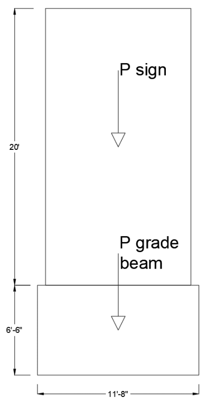
I´m actually freelancing right now so there's no office, but here are the elevations of the sign as you said.
Elevation_1_yg3u0z.png

Elevation_2_gveofa.png
 
Do some searching for cantilever beam natural frequency calculations. The formula you need is really quite simple. Here's some instructional material from MIT on the subject. That'll help you grasp the background and understand what your calculating. Some additional googling will give you the "plug and chug" version.

I highly recommend a copy of Roark's Formulas for Stress and Strain. A very handy reference to have on hand, especially if you're free lancing and don't want to shell out the thousands of dollars for FEA software. It breaks down a lot of the more complex situations (that would require FEA or long hand solutions to differential equations, etc.) and provides easy to use tables and constants for different boundary conditions.
 
Also, the foundation confuses me. Looks like you're resisting the moment at the foundation with a helical pile in bending?
 
Yeah I get the confusion, the pile cap or grade beam (not sure what to call it) is there because there´s a pretty steep slope along the sign but you can´t see it in the picture. It was an attempt to embed one of the piles in something solid instead of having it in the air, however, the grade beam is adding a lot of weight and cost to the design so I think I´m gonna eliminate it and design the pile considering the free length that it will have.
 
I'd be very surprised if that ~25' sign structure has a natural frequency under 1 Hz. I honestly would have called that rigid by inspection used a Gf of 0.85 and moved on.

What's the structure inside the sign? One pipe or HSS up the middle?
 
I'm with azcats on this one. Use 0.85 and move on. If you want to calculate the natural frequency of that structure on a spread footing. Easy. Should take you no more than 30 minutes. You want to calculate that frequency of that structure on piles, order of magnitude more difficult and you probably don't have all the soil-structure interaction information that you need.
 
Thanks everyone, I ended up using 0.85 anyway so I guess it was me trying to over complicate things, much simpler than I thought in the end.
 
Status
Not open for further replies.

Part and Inventory Search

Sponsor