structure_engineer
Structural
Based on ASCE Task Committee on Wind Induced Forces publication Wind Load Design for Petrochemical and Other Industrial Facilities (WLD for POIF), 2020, Section 5.2.1, the tributary area is based on diameter of the largest pipe, D, plus 10% of the pipe rack width, W. I have a series of pipes, 10 of them, all same diameter, of 54 inches, lay side by side for about 450 feet long. The typical spacing of support is 55'-9". So the bent width, if you will, is about 64', per the model. Can I use the same principle and treat the support system as a pipe rack? The height of point of support is about 10'.
On each bent, there will be a huge support beam across the width of 64', supported by 10 piles. Thus, each pipe of 54" has it own support pile. The pile is most probably driven open ended pipe piles, cut to the right elevation, with the wide flange beam field welded to the pipe piles. For the anchor bay, there will be a kicker brace, supported by a reinforced concrete grade beam.
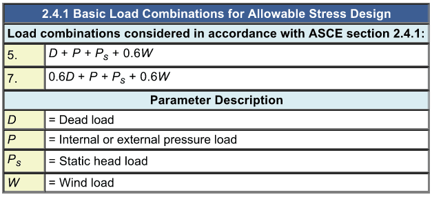
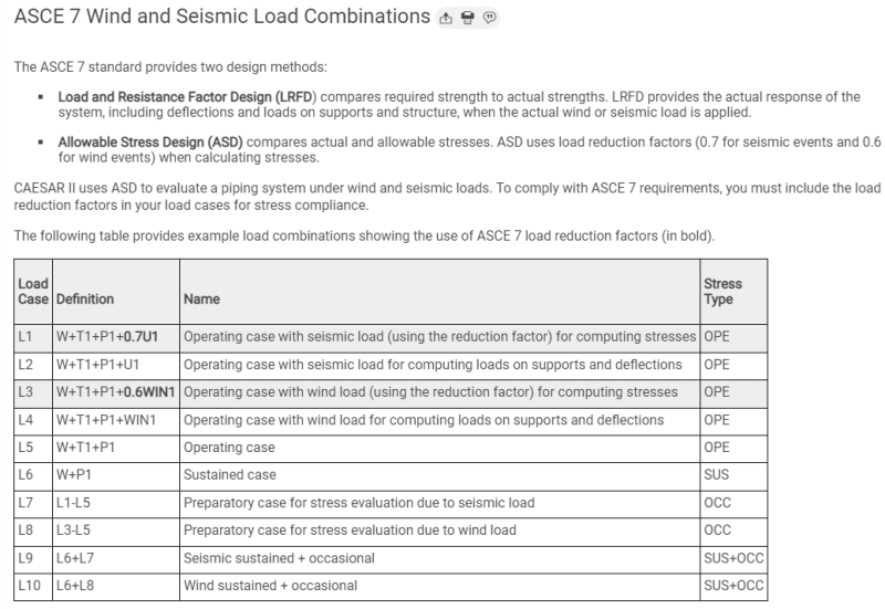
I did my own calculations of wind transverse to the pipes. I came up with 11 kips of allowable load to a typical bent. The actual wind load calculated is 18.3 kips (ultimate), based on the publication WLD for POIF. There are a total of 8 main bents. The equipment supplier of the pipe system came up with a total wind load of almost 10 times (verified, and not a typo) higher than my calculations. The software used is Caesar II, Version 12. I am asking your opinion on the principle of applying the diameter plus 10% width has its limitations? It is meant for pipe rack, which is typically not more than 30' wide, at the most. In my case, each bent is about 65' wide. I was wondering if the theory still applies here? We just had a brainstorming session amongst the structural engineers. The consensus is perhaps using a higher percentage. Instead of adding 10% width, say adding a 15 or even 20% width. What do you guys think? Your input is much appreciated.
Here are some criteria: Kz = 0.85, Kzt = 1.0, Kd= 0.85, V = 164, G = 0.85, Ht POS = 10', Width = 66', Bent spacing = 55.75', Cf = 0.7. In case you are interested in some numbers to verify how I got 11 kips allowable load, to each bent of supports.


