Continue to Site

Eng-Tips is the largest engineering community on the Internet

Intelligent Work Forums for Engineering Professionals

  • Congratulations KootK on being selected by the Eng-Tips community for having the most helpful posts in the forums last week. Way to Go!

Wind Load to Pipe Rack, ASCE 7-10: D plus 10% width

Status
Not open for further replies.

structure_engineer

Structural
May 5, 2022
46
Based on ASCE Task Committee on Wind Induced Forces publication Wind Load Design for Petrochemical and Other Industrial Facilities (WLD for POIF), 2020, Section 5.2.1, the tributary area is based on diameter of the largest pipe, D, plus 10% of the pipe rack width, W. I have a series of pipes, 10 of them, all same diameter, of 54 inches, lay side by side for about 450 feet long. The typical spacing of support is 55'-9". So the bent width, if you will, is about 64', per the model. Can I use the same principle and treat the support system as a pipe rack? The height of point of support is about 10'.

On each bent, there will be a huge support beam across the width of 64', supported by 10 piles. Thus, each pipe of 54" has it own support pile. The pile is most probably driven open ended pipe piles, cut to the right elevation, with the wide flange beam field welded to the pipe piles. For the anchor bay, there will be a kicker brace, supported by a reinforced concrete grade beam.

I did my own calculations of wind transverse to the pipes. I came up with 11 kips of allowable load to a typical bent. The actual wind load calculated is 18.3 kips (ultimate), based on the publication WLD for POIF. There are a total of 8 main bents. The equipment supplier of the pipe system came up with a total wind load of almost 10 times (verified, and not a typo) higher than my calculations. The software used is Caesar II, Version 12. I am asking your opinion on the principle of applying the diameter plus 10% width has its limitations? It is meant for pipe rack, which is typically not more than 30' wide, at the most. In my case, each bent is about 65' wide. I was wondering if the theory still applies here? We just had a brainstorming session amongst the structural engineers. The consensus is perhaps using a higher percentage. Instead of adding 10% width, say adding a 15 or even 20% width. What do you guys think? Your input is much appreciated.

Here are some criteria: Kz = 0.85, Kzt = 1.0, Kd= 0.85, V = 164, G = 0.85, Ht POS = 10', Width = 66', Bent spacing = 55.75', Cf = 0.7. In case you are interested in some numbers to verify how I got 11 kips allowable load, to each bent of supports.
 
Replies continue below

Recommended for you

Wind Load Design for Petrochemical and Other Industrial Facilities seems like it would provide good guidance in this case. Are your considering shielding for the pipes? You have 10 pipes and the equipment supplier is getting a load that is 10x what you got... seems like an odd coincidence. Also how was their calculation verified as you stated? If you verified them then it would seem you agree that the loading should be higher.
 
I'm betting vendor engineer is a mechanical engineer (uses caesar) who as stated above didn't use pipe shielding in his wind load calc.
My advice is to talk to the vendor engineer who did wind load and tell him how to wind load a piperack.
 
Shielding sounds good, but I've never known exactly when to stop applying it, either, and tend to ignore the effect in most cases.
Example: One handrail here, one handrail 30' over yonder- does one actually shield the other? Presumably not, but the normal codes don't tell you that, either.
In the case of the pipe designers, it may be advantageous to them to apply the same load to all pipes rather than having different loads on each one. That is, you wouldn't want to design it such that removing Pipe No. 1 at some point caused an overstress in Pipe No. 2. And it's obviously easier if the detailing and supports for each pipe are the same.
In the event that vibration entered into the problem, G could be considerably different from 0.85.
Two related problems I've seen- ASCE 7-16 gives info for the increase in wind loading on groups of vertical tanks, relative to an isolated tank.
And I've seen discussed the effects of two cyclists drafting each other (or riding a tandem)- with the issue of how close must they be for significant benefit.
 
I'm looking at my copy of "Wind Loads for Petrochemical and Other Industrial Facilities" by the ASCE Task Committee on Wind-Induced Forces, copyright 2011 (so, an earlier version of what you're looking at, structure_engineer). From the commentary on Tributary Area for Piping:

WL for POIF C5.1.1 said:
This area is based on the assumption that the wind will strike at an angle plus or minus from the horizontal with a slope of 1 to 10 and that the largest pipe is on the windward side. This corresponds to an angle of +/- 5.7 degrees...
WL for POIF C5.1.4 said:
The force coefficient C[sub]f[/sub], for pipe is taken from ASCE 7, Figure 6-21 [NOTE: This must be referencing ASCE 7-05] for a round shape with an h/D = 25, D*(q[sub]z[/sub])[sup]1/2[/sup] > 2.5, and a moderately smooth surface; that is Cf = 0.7...

A couple thoughts:

It appears that using a wind angled at 5.7 degrees from horizontal is the standard of care - instead of using D + .1*W, you could manually calculate the area due to wind striking at 5.7 degrees.

Also, you can go back to the Cf calculation for the pipe, and verify that the 0.7 is correct.

I would be pushing to use the reduced wind loads due to shielding that the WLD for POIF allows for, as that's been built off of the experience of engineers in that field (with the checks mentioned above). Your contract, however, may stipulate that you design the structure and foundations for whatever loads the piping designers are giving. You'll need to hash that out with your boss. Hope this helps!

Please note that is a "v" (as in Violin) not a "y".
 
AskTooMuch is correct. Talk to the vendor. My experience has been that most equipment vendor engineers don't really understand much about structural design.

Your method of D+0.1*W is the industry standard and like alluded to above accounts for a wind load that's not perfectly perpendicular to the pipe.
 
winelandv has a good point about the contract. You should ensure the contract/owner's criteria is not more stringent. I have had this happen where owner required the vertical plane of the pipe rack be taken as solid for wind loading. Owner was willing to pay for maximum flexibility on any future piping arrangement.
 
Really appreciate everyone taking the time to read the post and post their reply. I know everyone has a full time job, have their families, and busy living their life.

Here is the arrangement: the vendor talks to our paying client directly. We are not paying them. The client is paying both my company and the vendor. So it is hard to get them to comply and do anything for us since we are not the vendor's paying client. We are, as they (the vendor's engineers) addressed in the email to our PM, through their PM: "Customer." They have a Ph.D. title at the back of their name so who am I to argue with them? I am just a masters level. Some of you are exactly right, they are mechanical engineers running Caesars. We did try to engage with them, not once, but twice to provide a more concise and manageable result to us so we can use the results. I also asked for the results in basic load cases but got shot down.

I did a table showing the summary of results:

F Bay1 B2 B3 ANC B4 B5 B6 B7 TOTAL
VENDOR 35 143 238 78 267 20 12 11 10 814 kips

0.1D 5.3 8.8 11 11 11 11 11 11 6.5 86.6
0.2D 8.2 14.1 18 18 18 18 18 18 10.4 140.7
1.0D 31.1 56.2 70 70 70 70 70 70 41.2 549

When I said I verified the results, I meant I came up with what they said is the average Fz per finger, based on the summary of results they have provided. I took the pdf file and did an export to text file and did the summary in Excel. I made some manipulations in Excel and came up with the total of 814 kips, exactly as they had responded in the email. The went on to provide the 582.07 kips of total Fz computed by ASCE 7 hand calculations. No backup was provided as how the 582.07 kips of total Fz was obtained. They then quoted this: "Apparently, the difference is due to elastic deformation of the 'equipment name here' material considered in theoretical calculations with CAESAR II software".

I believe they apply the full wind pressure (42.3 psf) to every single pipe in the equipment / pipe. I am not sure if they use the full Kd = 1.00 or 0.85 as allowed by ASCE. I am at lost why is Bay 2 and the anchor bay is seeing more than 230 kips of wind load when the pipes are laying on the supports, sloping from Bay 1 to Bay 7, with the rest of the bays only have around 10 kips of wind load. What do you guys think? Thanks again.


I have some correction on the loads table:

F Bay1 B2 B3 ANCHOR B4 B5 B6 B7 TOTAL
VENDOR 35 143 238 78 267 20 12 11 10 814 kips

D+0.1W 5.3 8.8 11 11 11 11 11 11 6.5 86.6
D+0.2W 8.2 14.1 18 18 18 18 18 18 10.4 140.7
D+1.0W 31.1 56.2 70 70 70 70 70 70 41.2 549

The consensus among the engineers: use a higher percentage on the width. As shown above. I have used a D+20% width of the bent, instead of the 10% as recommended by Wind Load Design for Petrochemical and Other Industrial Facilities. That is a 62% increase on the Fz. I will also apply wind load to the 10 ft of pile sticking up above grade. That should pretty much covers it. Still could not figure out why there is so much difference. Your attention is much appreciated. Have a great weekend.
 
The piping guys are doing what is right for them. Applying the full wind load to each pipe is reasonable for their piping stress analysis. Unless they are giving you combined results for your rack, there's no reason they should be reducing their loads.

Their loads are valid for the purposes they're using them. It would be a bad choice to assume shielding for piping design, because what if pipes are removed and an interior pipe becomes an exterior pipe?

That doesn't mean you have to use their forces for overall design. If the guide clips are your responsibility, make sure all of those can take the point load they've given you. Then feel free to design for reduced loads on the beams and lateral system based on the reduced wind area. If you're concerned that the spec disagrees, write a design basis of some sort explaining what you're doing and send it to the client for review.

This is the same as things like frictional loads. The stress analysis is going to give you a frictional load at each support point, but you can reduce that along the lines of industry practice as you travel through the lateral system.

At the end of the day, though, it's not that big a deal if you end up designing to the full wind load. I've had lots of situations where things are spread out and you don't have anything close to shielding happening. It's not ideal, but you'll make it work. If it turns out people put heels in and don't want you to do it, then document it and keep going.

However are people actually telling you not to do what you want to do here? Is the piping guy telling you not to do what you're saying you want to do, or is he just saying that his calculations are not wrong? They're not wrong, they're just not targeting towards the problem you're solving.
 
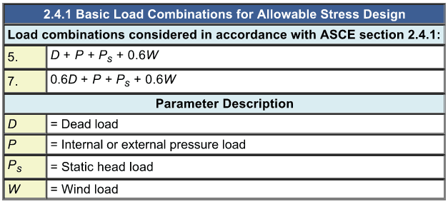
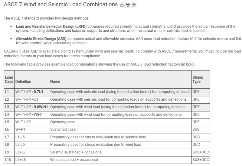
I am starting to design the foundation to support the pipes. I have uploaded the load combinations posted by the equipment vendor. They are using ASCE 7-16 for wind load. By looking at the load combinations, I think they are mixing allowable with ultimate. ASCE 7-16 wind is ultimate or strength level. The weights of the pipelines are allowable (correct me if I am wrong.) Thus, the load combinations presented is not valid because you could not mix allowable with strength level load cases. The operating condition of should have a 0.6WIN1 and 0.6WIN2 load factors. Then the load combinations are on the same level. Your input is much appreciated.
 
 https://files.engineering.com/getfile.aspx?folder=32553b11-cac1-4def-8340-3ae03870f014&file=All_Load_Combinations.pdf
In any normal world. The fabricator lists the actual (nominal) weight. This should be taken as D for either LRFD or ASD load combinations.
 
To bring the nominal weight into the load combinations, if it is dead weight the factor would be 1.4? In the attached document, for load combination #46, the correct load combination should be W+T3+P2+0.6WIN1? So is load combination 48, there should be a 0.6 factor associated with all wind loads.

In COMPRESS Pressure Vessel Design Calculations, they actually show this:
2022-12-29_09-34-59_yxoxwu.png


Mixing up strength level and allowable stress design load factors are not allowed as far as I know. That is just the very basic.
 
They specified at the top of their combinations that WIN1 and WIN2 are ASD wind loads. TO me, this says they already multiplied the wind load by a factor of 0.6 and that is why it is not showing up in the load combinations.
 
For the purposes of analyzing pipe support structures (i.e. pipe racks - the structural steel), I calculate the wind load based on 1.10 times the diameter of the largest pipe in accordance with ASCE 7-10. I don't apply wind loads to every pipe because the ASCE has determined it's not necessary.

For the purposes of conducting a pipe stress analysis, I would apply wind to each individual pipe (even if one of the other pipes would provide shielding). There's always a chance that other pipes on the rack would someday see wind if the largest diameter pipe were removed.

If I were basing my applied loads off of the reactions provided by whoever performed the pipe stress analysis, and if the wind load reactions they provided were just the sum of the wind on every pipe, then I'd likely disregard the wind loads in their reaction sheets and calculate it myself. I'd include the other loads though (e.g. dead load, seismic load, ice load, thermal expansion, etc).
 
Status
Not open for further replies.

Part and Inventory Search

Sponsor