Continue to Site

Eng-Tips is the largest engineering community on the Internet

Intelligent Work Forums for Engineering Professionals

  • Congratulations KootK on being selected by the Eng-Tips community for having the most helpful posts in the forums last week. Way to Go!

Wind uplift on aluminum decks (balconies)

Status
Not open for further replies.

structural-eng

Structural
Jan 26, 2017
39
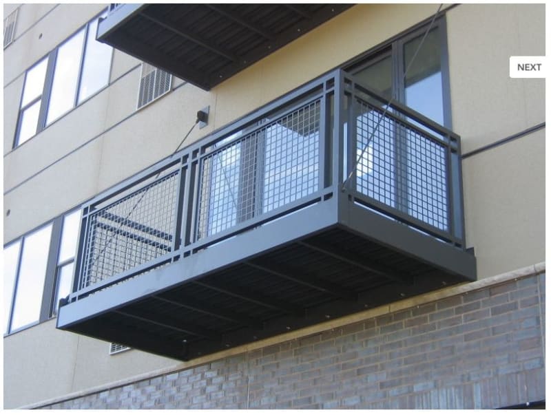
We have been designing prefabricated aluminum decks for a local fabricator for a few years now. If you drive around any metropolitan area you have assuredly seen hundreds of these decks as they are all over mid-level wood constructed housing units. You know, the ones with the hanger rods at the outer corners that go back to the building wall.

We have always designed for 60 psf live load (1.5x occupancy served), flat roof snow (for an unheated surface) plus snow drift and for uplift. The only thing that the uplift governs for is the hanger rods as it puts them in compression. Our client has tried getting us to allow 3/4" diameter rods for the hangers on numerous occasions claiming that ALL the competition uses 3/4" diameter rods. The rods are typically A36 steel or stainless steel (they take care of the dissimilar metals condition at the yoke. We have never been able to justify 3/4" diameter rods. We have always used 1" diameter. Even at an net uplift pressure of 20 psf the compression in the rods is about 260#. The rods vary in length/angle but the last one we did the rods were 128" and you can't get 260# out of a 3/4" diameter rod that long.

I'm curious if anyone has any insight on how other manufacturers can be justifying 3/4" diameter rods? I've seen drawings for 2 other companies and they do use them. We talked about this in house numerous times and believe it's very possible they are neglecting to consider the uplift case but we don't believe that is acceptable.

The other drawings I saw showed the ledger with prefabricated holes at a given layout and it was the purchasers responsibility to ensure there was adequate backup for attachment. I'm pretty sure with the competition deck no one actually designed the fastener that connects the deck they are buying to the building. I've been doing these long enough to know that rarely does the same connection location work on 2 different buildings because of how the exterior walls are framed at the floor levels. We adjust the layout and fastener type to work with the way the building is framed for each project. This lack of attention to detail by the competition just adds to my belief that they aren't considering uplift. Maybe I'm wrong. I would love it if someone corrected me and pointed out some snip in the code that said the uplift condition could be neglected for these decks but I'd be surprised if that was the case.

Thank you.
 
Replies continue below

Recommended for you

From what you described, you are providing a better (and quite possibly safer) product. I'll admit I'm not familiar with what you're talking about as a deck - I've designed something that I think is similar but only as small canopies over exterior doors.

It may be that the competition is assuming some amount of fixity at the wall for the ledger connection. This seems like a terrible idea if they just do a standard ledger and tell the installer to figure out the rest, though.

Unless they can furnish the competition's calculations for review, stick to your guns. There's no shortage of stories out there of this type of structure failing in uplift.

 
I'd love to know if people are actually getting those to calc out as well. I see stuff like that all the time in arch drawings, but fortunately not frequently enough that we have gotten much pushback when we change it to something that works.
 
They probably are not checking uplift. I would continue designing the way you are unless there is some code provision (which none of us know about) that allows me not to. Like phamEng, I run into this with small 3' to 5' canopies and occasionally a balcony. No telling how your competition justifies it but here are some possibilities of what they may believe. I am not saying they are correct, but they may believe one or more of these things.
[ul]
[li]In reality, the canopy will never see the full design wind. So a little fudging is ok. Even if it did, who could prove the actual magnitude when it failed?[/li]
[li]In the ASD world, they ignore .6D+.6W combination. After all, the DL is actually present they state and since the balcony is such as small area, they can easily confirm the total DL will be present. If you change it to D+.6W, possibly no uplift.[/li]
[li]When the wind picks up on the balcony, it only lifts a little and then comes back down. As it lifts, the horizontal projection gets to be less. This reduces the lift as it raises up.[/li]
[li]The wall connection has some fixity.[/li]
[/ul]

I think them worrying about 1" rods versus 3/4" rods is foolish to start with. I realize they cost more, but not that much more. I run into this all the time where Clients show me some other design and think mine should be the same. Magically, the other design is always cheaper than mine. They compare 2 items, and for some reason think the cheaper one is correct and the other one is overly conservative.

Worst one I ever had was a very hilly site they were building 2-story brick apartments on. They wanted to build the buildings first and then fill the property to make it fairly level. All I was designing was the foundations for the buildings. The site engineer had a typical property retaining wall detail that showed a 5' wide foundation for a 10' tall property only retaining wall. They wanted the buildings to all be Slab on Grade. The property was sloped so much, I had buildings that varied from 3' to 10' from the ground elevation to the 1st floor level. My footings at the 10' tall SOG were naturally much more substantial. The Client wanted me to change my foundations to match the site engineers retaining wall footings stating "These are identically the same conditions". I told them that the retaining wall did not have brick, did not have a 2 story building literally on the edge of it etc. That did not matter, someone told them this was the same. My next logic was, since these are the same, why are you not making the property retaining walls the same as I show? Since I would not change, they have never used me again. But, I can do without the lawsuit and potential loss of life when compared to a future meager fee.
 
Ron247 said:
In the ASD world, they ignore .6D+.6W combination. After all, the DL is actually present they state and since the balcony is such as small area, they can easily confirm the total DL will be present. If you change it to D+.6W, possibly no uplift.

I suggest check the net uplift using combination D+W, as the design could be dated way back then.
 
I appreciate all the responses and welcome anyone elses input on this subject.

With regard to the combination of dead load and wind, there is very little difference between 0.6DL and full DL because the decks are aluminum. The actual dead load is less than 5 psf.
 
Do you have a picture of one of these? 5psf sounds right for an aluminum canopy, but I can't imagine something truly strong enough to support a 60psf live load with only a 5psf self weight.

Retired - D+W wouldn't be an accurate check as the code provisions since 2010 calculate a strength level wind load. If using ASD, 0.6W is appropriate. If LRFD, it would be 1.2D+W(down-load, if applicable) or 0.9D+W(uplift).
 
I don't have a picture of one of the decks that I have designed but it's very similar to the one below which I found online. The 5 psf dead load is conservative. The aluminum decking is 2.2 psf. The joists are less than 1 psf effective. These decks aren't overly large (approx. 5.5'x8.5') so the members aren't either.

Alum_deck_qwfmxl.jpg
 
Coincidentally there is another thread going on about the same thing, though from an SEOR's point of view and how to attach the thing to the structure.

A picture that came up shows the handrail for the balcony attached to the wall near the top rail. Is that how your competition is doing it? Looking at the handrail as some sort of Vierendeel truss that can take a compression load during uplift and then assuming the rod is only carrying tension loads? Seems somewhat plausible, though it would complicate things for the designer and the EOR to save just a little bit of steel. I guess if you're manufacturing a thousand of these things a month it might make a difference... Just a thought.
 
Fair enough. I guess it is aluminum, after all. I haven't done much design in aluminum for 5 or 6 years, so I forget just how light it is.
 
I'm not aware of them fastening the railing to the building but it's an interesting idea.
 
The railing keeps it from uplifting is another possibility even if you do not fasten the rail to the wall. It pushes on the wall in uplift conditions.
 
In the photo, is there a row of anchors at the bottom of the connection to the wall?
 
phamENG,

When the 0.6D combination was first introduced, the resistance was high (at least in my office), especially for some application like this. The argument was, in reality, if the balcony lost some support members (accounting for the 0.4D), it wouldn't be allowed in service, so wind does not matter at that point of time. In another manner, if the balcony lost flooring accounting for the 0.4D, the wind just will not be there, and again, the balcony is out of service anyway. The engineer working for the competition maybe one of my generation, the design was done way back then - using D+W.
 
structural-eng said:
The actual dead load is less than 5 psf.

What is the material of flooring - aluminum?

Check the D+W combination, if the 3/4" rod is only slightly overstressed (within 5%-10%), the argument I put in response to phamENG may have been used to justify its application in this case. I've seen justification for over stress up to 15%.
 
retired: I thank you for your service to our profession and the knowledge you pass on to those of us of a younger generation, but I must respectfully disagree with your justification. On its face it seems like a very logical approach, especially in a case like this. In a large building it can be difficult to accurate compute dead loads and we often make conservative assumptions for gravity loading, so applying the 0.6D would seem to help to clear that conservatism out for the uplift calculations. Here, though, it is manufactured in a controlled setting and, hey, you can even weight the thing on its way out the door, right? To quote ASCE 7-10, though:

ASCE 7-10 said:
Load combinations (7) and (8) address the situation in which the effects of lateral or uplift forces counteract the effect of gravity loads. This eliminates an inconsistency in the treatment of counteracting loads in allowable stress design and strength design and emphasizes the importance of checking stability. The reliability of structural components and systems in such a situation is determined mainly by the large variability in the destabilizing load (Ellingwood andd Li 2009), and the factor 0.6 on dead load is necessary for maintaining comparable reliability between strength design and allowable stress design.

By using pre-ASCE 7-10 W or ASCE 7-10 and later 0.6W (essentially the same load) in an ASD combination, you are only looking at a 50 year MRI for the loading whereas LRFD is looking at a 700 year MRI (for Risk Cat. 2 buildings, higher for 3 and 4). If you neglect the 0.6 factor on the dead load, your resulting structure is significantly less resilient than one that is designed per the code requirements. I suppose you can argue the need for such a return period, but I don't think any engineer advocating for less resilient structures will find him-/herself on the right side of history.

As for this specific application, I don't think it matters. D=5psf. 0.6D=3psf. I don't think 2psf will make much of a difference in the net uplift.
 
phamENG,

By no mean I want to pass and defend the argument addressed, but to point out the thinking, and practice, at that particular time by some (me included). However, engineering judgement is the point I want to press on. As opposite to rigid code provisions, that try to cover all events by a single factor; engineering judgement is based on our understanding and conviction on certain event, and the call should be made in case by case manners. I personally prefer an engineer knows how to think, rather than blindly follows/relying on code provisions without understand the full context of the code provisions.

If the check I suggested turns out the result lies in the borderline situation I have suspected, I believe engineering judgement should be be called to justify, and settle the issue.

We used to joke around the 0.6D combination, saying it was coded with focus set more on manufactures and politicians wishes, rather than design needs. Well, let me end here, since I agree everthing you have said.
 
Another phenomenon I would like to point out is, when the balcony lift a little due to wind, the tendency of the rod is to bend a small amount to adjust to the new geometry. The deflection occurs in very short duration, and usually is unnoticeable for the naked eyes. The energy will likely be relieved through the deflection rather than causing outright buckling of the rod.
 
retired, I understand and see your point now. Thanks.

It may not bee 100% applicable to the case of these decks, but on similar canopy structures that "relief" can have profoundly negative effects. Depending on the magnitude of the deflection or, if the rods do buckle elastically, when the gust passes and canopy drops again, they'll straighten and you can end up with a shock loading on the rod connections. The magnitude of the shock may be small or large, but when you consider the potential for water intrusion due to difficult flashing conditions, the connection may not bee all you think it is (especially in wood construction).

 
Status
Not open for further replies.

Part and Inventory Search

Sponsor