Continue to Site

Eng-Tips is the largest engineering community on the Internet

Intelligent Work Forums for Engineering Professionals

  • Congratulations cowski on being selected by the Eng-Tips community for having the most helpful posts in the forums last week. Way to Go!

Wire Strand Concrete Reinforcement - Existing Concrete Floor Slab 2

Status
Not open for further replies.

rcatalina85

Structural
Nov 28, 2011
8
Hello,

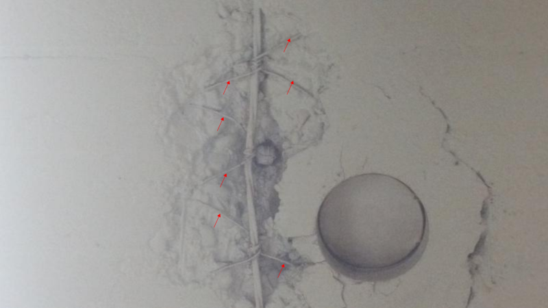
I am currently evaluating an existing concrete floor slab that I am told was constructed in the 1950's. I found an area of exposed reinforcement and it appears to be wire strand that could be a pre-stressed or post tensioning cable. No signs of any "pockets" and the slabs are supported by structural steel beams spaced at 6'-3" oc. The short span does not make sense with either of these systems, but I have not seen this type of reinforcement used in conventional structural slabs.

I would appreciate any guidance or references that might help pin-point the original design intent for this type of slab.

20170711_132749_ryqxzo.jpg
 
Replies continue below

Recommended for you

rcataline85:

Your photo is not particularly clear. Slab soffit, right?

Looks like 2 wires (or maybe 3 wires) 'stranded' around each other.

3-wire strand is still used today in some markets like the UK, however, its use is restricted to precast pre-tensioned applications, as far as I know.

For your case, I seriously doubt it is POST-tensioned, as the photo shows no evidence of a duct (if grouted), nor sheath (if unbonded).

Are the slabs possibly precast, and hence the wire strand is PRE-tensioned? I doubt this too, since there is a definite 'kink' in the wire at the center of the photo.

Also, prestressing strand was not generally available until late 50's/early 1960's in the US - predominantly 1/4" dia. plain high-tensile wire systems with button-heads for PT systems until mid-60's.

Looking at the photo in a bit of detail, it looks like chain-link 'fencing' to the LH and RH side of the longitudinal wires:

chain_link_kyxrm7.png


Bit of a mystery.

Have you looked at Structure Magazine articles on 'Antiquated Structural Systems'? I may have a link that I can dig out for you that may be of assistance.
 
I thought it was the top of the slab. My first thought was the type of precast form slab with bottom reinforcement, and trussed top steel to support cast in place topping. Not sure if that type system was in use in the 1950's.
 
This looks like it - 'Triangle Mesh Concrete Reinforcement' by American Steel and Wire Company:

Capture2_d00iyc.png


Not sure what dates it was used, nor which part/s of the US.
 
...and if you want to get into the archives of the 'Triangle' reinforcement system this Link will enable you to review all the system data and load test info for testing that was conducted around 1910 in NY City:

Capture1_x9umxn.png
 
Those NY City test reports of the 'triangle mesh' system are fascinating.

This is a system and testing conducted more than 100 years ago!!!

The System H - for warehouse loadings - used 4" thick slabs, spanning 6', #4 gauge cold-drawn steel wire @ 4" longitudinal c/c...and was load tested to 4,000 psf without failure. Not a typo - 4,000 psf!!!

Capture1_ybaxks.png


That is 9-1/2 feet of stacked pig iron stacked.

Capture2_c3zhv9.png


Testing was discontinued as the stacked height of the pig iron presented a safety concern for the workers.

They minimized arching action by using beams upon the first layer of pig iron to distribute the applied loading.

Capture3_l248p0.png


The final deflection was 1-1/8".
 
All,

Thanks for the great input, and thanks Ingenuity for the information on the triangular mesh. I believe this may be what was used and I will look at the resources you have provided to determine what grade the strands were in that era. The only thing that still has me thinking is it appears the slab was designed as a one-way slab with more reinforcement strands in one direction. Not sure if that is how the triangular mesh was used. I appreciate everyone's input and resources.
 
Yes, it is a one way reinforcement system. And you should thank Ingenuity by giving him a star.
 
rcatalina85:

This document may help: "Engineers' Handbook and Catalogue on Triangle Mesh Reinforcement for Concrete" by American Steel & Wire Co. from Feb 1908: Link. It is a free Google Books scan that you can easily view in Google Play. You may be able to download it - not sure.

rcatalina85 said:
...it appears the slab was designed as a one-way slab with more reinforcement strands in one direction. Not sure if that is how the triangular mesh was used. I appreciate everyone's input and resources.

Yes, they were designed for one-way action - with longitudinal wires in the main span direction, and the 'triangular mesh' cross-wires taking care of temperature and shrinkage effects in the transverse direction. I assumed they lapped the mesh by some min. dimension in the transverse direction.

The mesh was available in 18" through 58" wide rolls. The longitudinal wires were in 1, 2 and 3 wire arrangement (2 and 3 wire options being 'stranded'), with several gauge options, and a wire-group spacing of 4". The cross wires were typicaly 12-1/2 gauge at 2" or 4" spacing options.

From pages 110 and 111 of above reference:

Capture1_m2iql3.png


It seems the system was designed for typically negative moments over the supports of wL2/10 or wL2/12, depending if first-interior support or full-interior supports, and used working stress methods. However, I do recall seeing in the past a 'draped mesh' system (it was NOT the 'triangle mesh' system) that used a catenary equation to determine the slab capacity, so you may wish to do some digging around to see if that is applicable. ACI 318 historical copies are available from 1908 in digital form here: Link

rcatalina85 said:
determine what grade the strands were in that era.

From the above reference:

Capture_hlam9z.png


I think it was to ASTM A-82.

The above reference does state that higher yield and ultimate strengths wires were available, where required.

If you need to establish the existing system capacity for a proposed increase in loading I would suggest you take some samples of the longitudinal wires and have them mechanically tested to establish the yield and ultimate tensile strengths. % elongation at fracture is also a meaningful property to have from the testing. We have removed 7-wire prestressing strands from existing buildings successfully and had them tested for mechanical properties. You will need to check with your lab on min. sample length, and how they grip the sample in the test assembly jaws - often you will need a sample length of a few feet (for 7-wire strand it is about 54").

Probably worth taking a few concrete cores samples too the get a handle on the compressive strength.
 
Here is a link to archive.org that enables you to download a PDF copy of the same 1908 document I reference above on Google Books: Link

capture_pl9gej.jpg


It is about a 50 Mb file size - too large to upload to Eng-Tips, I think.
 
Status
Not open for further replies.

Part and Inventory Search

Sponsor