cavitate
Civil/Environmental
- Aug 12, 2008
- 53
It is a bit more complicated than that, I have disassembled a 4 section FWD/OFF/REV switch and need to reassemble it.
With the pictures and drawings I have, I can wire the switch just as it was originally.
The problem is putting the switch back together with the cams located properly to close the proper contacts for FWD and REV.
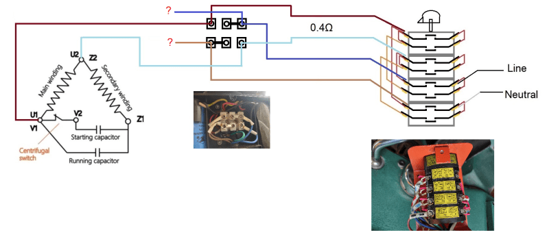
I'm sneaking up on a wiring diagram of AC in, switch with all contacts, and 4 wires from motor.
Please confirm or correct the two capacitor motor schematic matches the Harbor Freight milling machine motor.
The above is a poor question for this forum, I have moved from a milling machine forum, but maybe...
The drawing below has the two wires that measure 0.4Ω connected to the switch.
My thinking is that those two wires go to the Main motor winding.
Please confirm or correct that if I'm wrong.
I don't know where the other two wire go to on the two capacitor motor diagram.
Anyone have input on that?
Thanks, Mikek

