Eng-Tips is the largest engineering community on the Internet

Intelligent Work Forums for Engineering Professionals

Wood Beam Scab Repair Calculation Example 3

Status
Not open for further replies.

LowSpark

Electrical
Jan 31, 2015
23
0
0
US
Hello All,

I have a question as to why every example of a beam splice shows the load in tension as shown in this link:

Kootk from this forum gave the solution to use a beam splice in this thread but no calculation example:

The only place I have found to talk about the load perpendicular to grain is this website which used a prescriptive approach:


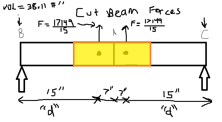
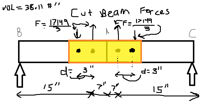
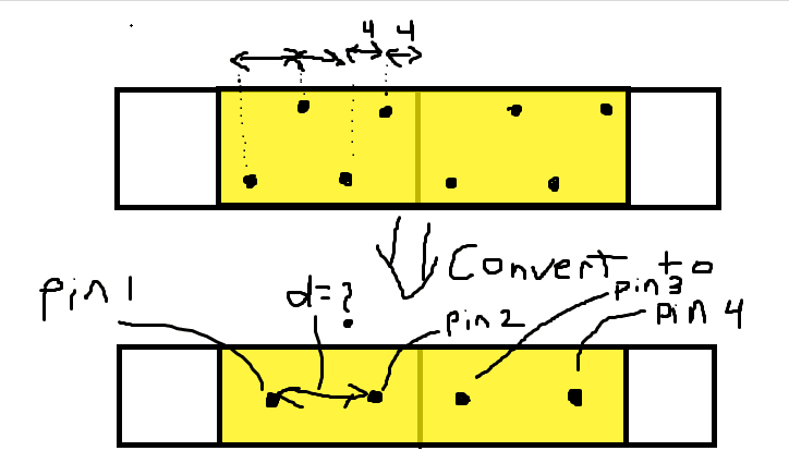
So my question is, why isn't there an example of the calculation shown in link one ( but with a uniform distributed load along the splice(such as the modified picture attached)?


Replies continue below

Recommended for you

BAretired

Thank you so much for taking the time to walk through all this. Its been a long time since I have done any kind of problems like this so I appreciate the patience.

Your last comment about the shear clicked!

You are getting the additional shear force that needs to be accounted for because of the moment and shear diagram of a simple beam. Since the bolt groups are not in the exact middle, they are going to see shear based on the following formula:

image_lbxwa9.png


Just one clarification to drive the point home:

"d" in your description above is it this:
image_p2m38j.png

or this:
image_nioo9d.png


I tried to change the numbers to that they can't be confused and each value is unique.

If it is the second option above and you have staggered bolts on each side of the cut, how do you convert the system to two pins? I can understand finding the bolt group center, but not sure how it can be converted to two pins. Here is a graphic of what I mean:
image_pau7zq.png
 
I will number your sketches Fig. 1, 2a, 2b, 3a, 3b.

Fig. 1 shows the variation in shear for a uniformly loaded beam and is the reason why shear at Pins 1, 2, 3 and 4 are not zero.

Fig. 2a is incorrect and illustrates a mechanism.
Fig. 2b is correctly showing 'd' and the cut beam forces. The dimensions on the bottom are incorrect as they don't add up to 60" which is the original assumption and the basis for determining M = 17,149'#.

Fig. 3a illustrates a 4-bolt arrangement between the scabs and each half beam section. It is not the most efficient way of transferring moment. It would be better to spread the bolts out to maximize the distance from each bolt to group center. If, for some reason, you had to maintain the arrangement shown, the force in each bolt would be proportional to its distance from the group center, meaning that some bolts would be under utilized.

Fig. 3b shows four pins, each pin at the centroid of a group. The moment resistance of each group is neglected with this approximation, i.e. a pin has no moment resistance whereas a group would have a small moment resistance. The force on each pin is M/d plus a correction for shear. F1 and F4 are upward on the scab; F2 and F3 are downward.

BA
 
BAretired,

I think that clears everything up for me.

I sincerely thank you for your detailed information and your generosity to share your knowledge with the community. You are a great asset to this forum and to Engineers as a whole.

Have a great rest of your week and stay safe during these uncertain times.
 
Status
Not open for further replies.
Back
Top