Continue to Site

Eng-Tips is the largest engineering community on the Internet

Intelligent Work Forums for Engineering Professionals

  • Congratulations SDETERS on being selected by the Eng-Tips community for having the most helpful posts in the forums last week. Way to Go!

Wood connecttion

Status
Not open for further replies.

bonbon83

Structural
Aug 3, 2021
17
Hi guys,
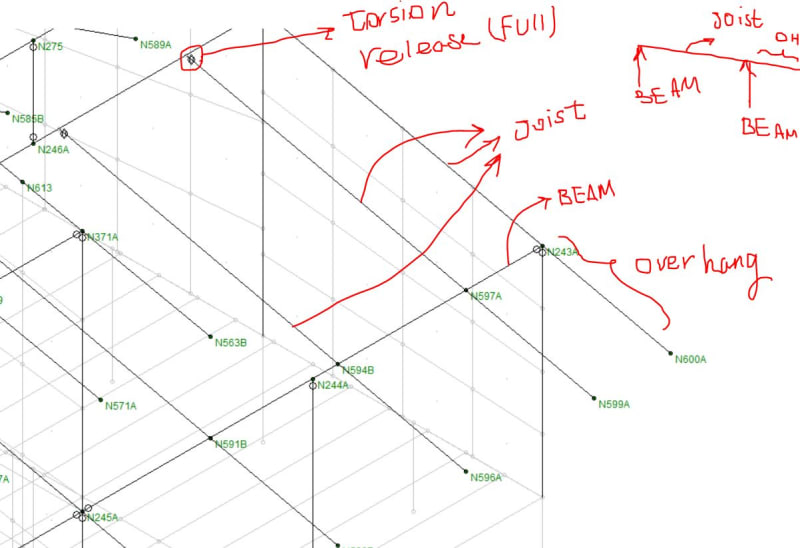
I would like to know how to model two types of connection first one is the joist hanger and the second one is joist over the beam connection I am worried about the torsion that happens on the joists and the beam torsion causes shear stress and Risa will fail the member because of that I’m wondering what would be the best practice to consider that torsion ? is it good to use torsion release at the end of the beams?

Thx
 
Replies continue below

Recommended for you

Bobbon83 -

So, the torsion is caused because the hanger is offset from the centroid of the beam. Essentially, the joist imparts it's shear at the face of the beam (or reasonably close to it), correct?

If so, I'd suggest that this is NOT something that is usually considered. Wood framing can sometimes create torsion in the structural model. IMO, this is usually a modeling problem rather than a real problem that would exist in the structure. It's just relatively difficult for wood connections to carry any moment or torsion.

However, if you really want to look at it, then you can create an "end offset" in joist equal to whatever eccentricity you want to use. You would also use a moment release at the end of the joist.

A lot of people don't realize that end offset and moment releases can applied at the same location.

Regarding a torsion release at the end of the beam: yes, this is often a good idea. If that beam is seeing torsion and the end connection of the beam is not capable of resisting that torsion, then it makes a lot of sense.
 
Thank you JoshPlumSE

Regarding the joist hangers, you are correct, the joist imparts its shear at the face of the beam, hence, I will use bending moment release. and thank you for your advice on beam torsion release now my problem in modeling:
for the joist sit on the beam connection which usually comes with overhang (i guess you did not address that? :)), my question is regarding the release condition at node (where joist seats on beam): I am assuming no moment from the joist should be transferred to the support beam, how can I do that in RISA3D? If can release that moment then there would be no torsion on the support beam, I modeled the joist as one member and put a node at beam connection, please let me know the best way to model that in RISA3D. I also attached snipped from my model
Capture_db1kju.jpg
.
 
bonbon83 said:
I am assuming no moment from the joist should be transferred to the support beam, how can I do that in RISA3D?

Thank you for the picture, I wasn't quite grasping your situation. But, now I see it clearly. This can definitely be a tricky thing to mode. My thoughts:

a) Ideally, you model it as you have shown and the torsion in the beam does not cause a failed shear check in that beam. It's true that this is probably not what will happen in reality, but if the torsion is minor, then you can live with some poor behavior in your model.

If the behavior is more significant, there are ways to get rid of it.

b) Honestly, the easiest way is to just NOT model those joists at all and directly enter the vertical reactions onto the beams that would occur if you had modeled the joists.

c) The other way is that you could use nodal slaving or nodal constraints to tie the joist to the beam rather than directly connect them. Because the two members do NOT actually share any nodes, they will not be automatically linked together by the program. This allows you to directly dictate how the degrees of freedom for the joint linked and, therefore, which forces are transferred between the members.

Attached is a small RISA example where I have done item (c) and shows how I use nodal slaving (RISA's term) to selectively constrain the joints of the joist back to the beams. Note that I have modeled these with a 2 foot offset to make it clear that there is not connection between these members other than the nodal slaving.
 
 https://files.engineering.com/getfile.aspx?folder=c27e0000-dcdd-4e93-ac58-9f2e81550abd&file=Nodal_Slaving.r3d
On situations where I need a pinned connection but also need to model the beam as continuous (so in your case your joists) I've sometimes used small gaps that are filled with rigid links. the rigid link would be fixed at it's connection to the beam, but rotation released at the connection to the joist.

But I'm kind of with Josh's b) suggestion. I likely wouldn't of modelled every joist.
 
Thank you JoshplumSE for your advice and the RISA file. it was very enlightening. your model makes sense to me. I like option c because I can use the area load concept in RISA to calculate the wind, dead, and snow load automatically within a LC.
Jayrod12 thank you for confirming.
 
Status
Not open for further replies.

Part and Inventory Search

Sponsor