Continue to Site

Eng-Tips is the largest engineering community on the Internet

Intelligent Work Forums for Engineering Professionals

  • Congratulations waross on being selected by the Eng-Tips community for having the most helpful posts in the forums last week. Way to Go!

Wood Diaphragms in FEA Models 1

ntn94

Structural
Apr 2, 2019
8
Does anyone have a resource or method for modelling wood diaphragms in FEM software such as Etabs? I assume the way would be to use a "semi-rigid" diaphragm and set it to 0.75" thick or whatever your sheathing thickness is. The tricky part is defining "wood" as a material and/or tweaking the stiffness parameters to achieve the proper load distribution to the lateral elements. Has anyone had success with this or know of a woodworks, awc, etc. design guide?

It seems shear walls may even be a bit more complicated than diaphragms but if you're doing wood diaphragms and walls, its probably way easier to just do it by hand. But for wood diaphragms with steel LFRS, it would be handy to use Etabs auto-wind/seismic loads and have the loads distributed to the steel element such that Etabs can design the steel for you. Any advice on this topic would be appreciated.

*For reference, this comes up on high-end residential projects where there is often a full steel skeleton infilled with wood joists and sheathing. Often the LFRS is steel MFs or BFs as walls either don't stack or are very minimal to maximize openness within the space.
 
Replies continue below

Recommended for you

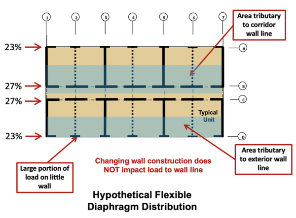
I'm in a low wind and seismic area. I do a fair number of houses like this and never consider the diaphragms to be anything but rigid. I distribute the loads by hand and model the frames in my 2D program. I can't imagine that a full model would be anymore accurate considering all of the other interior walls etc that are not modeled.

edited: I really meant flexible not rigid. I just distribute loads according to trib. areas.
 
Last edited:
I just use hand calcs. I asked Woodworks about this directly in 2018 and they said there's no way to do it within common FEM software like ETABS. I have thought about it like you have, considering a semi-rigid diaphragm with tweaking G and stiffness values, but I'm going by what the authority on wood said here. I don't want to step into a landmine of modeling something unconservatively. Maybe things have changed since 2018.
 
RFEM can do wood diaphram analysis in their floor module, but unless you are doing some complicated shape it is hard to justify the cost.
 
The NDS's Special Design Provisions for Wind and Seismic (SDPWS) has a section on how to modify G based on nail spacing and such to get reasonable good elastic behavior for design. This would be for the semi-rigid (or semi-flexible) modeling approach.

Of course, lots of people will choose the simpler route and classify it as either flexible or rigid. If you model a Flexible diaphragm in an FEM program, you just want to soften up your diaphragms.... then look at your deflections to make sure the diaphragm is soft compared to the frames / walls. That should get you decent behavior... even if it's not 100% flexible.
 
Thank you all for your responses, I'll likely proceed with a flexible assumption moving forward and perhaps compare a hand example to a "softened" diaphragm approach in Etabs and see what that yields.
 
Another thing you could consider is running a rigid and flexible case, and taking the larger of the two for sizing for strength. Overall deflection calcs can be done the same way, but may be a little too conservative when trying to hit your storey drift threshholds.
 

Part and Inventory Search

Sponsor