Eng-Tips is the largest engineering community on the Internet

Intelligent Work Forums for Engineering Professionals

Wood Drag Details 2

Status
Not open for further replies.

reverbz

Structural
Aug 20, 2024
34
0
6
US
Hey Guys, I have a couple of questions regarding drag in wood buildings(and in general).

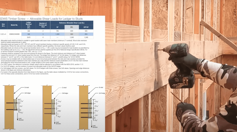
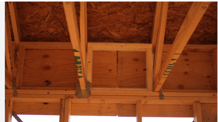
1. When using blocking in the diaphragm for drag/development into the diaphragm, all of the blocks need to be connected with a strap right? Or can you just use the diaphragm nailing into them?

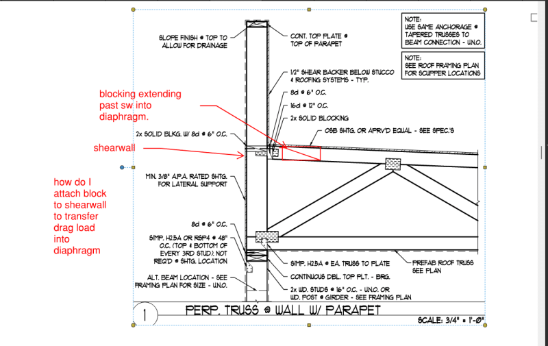
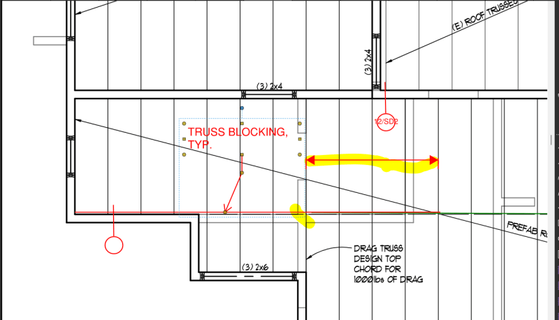
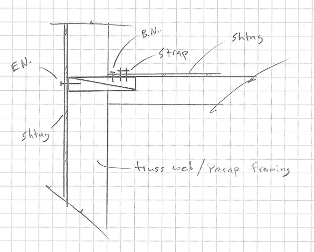
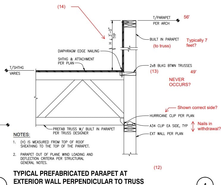
2. I have a perpendicular truss detail(see attached image)where the perpendicular truss is forming the parapet, and therefore, part of the shearwall. I'm trying to find a good drag connection here for the blocking to continue on in the diaphragm, could anyone point me in the right direction on this?
 
 https://files.engineering.com/getfile.aspx?folder=e338a481-1b06-4ae2-aa9f-b83285864175&file=perp_truss_detail.png
Replies continue below

Recommended for you

1) how does the tension go from one sheathing panel to the next? Your blocking and sheathing will break at the same spot.

2) I'm not sure what you're trying to do. Can you sketch it out a little more? Also, it's a lot easier for everyone if you put the picture 'in line' with your post using the Image button.
 
@phameng

Gotcha, and I've attached an image with a few markups added. Not sure if that helps but basically trying to understand how to attach a perpendicular truss into a shearwall and transfer the load into blocking to develop it into the diaphragm

Screenshot_8_uu9dsl.png
 
Your detail has blocking at the sheathing edge, and blocking in the wall.
You also have them nailed together. The shear (into and out of the page) is transferred from the sheathing to the vertical blocking and the vertical blocking to the horizontal blocking, finally the shear ply is nailed off to the horizontal blocking.

That is your load path for shear (into and out of the page).

Your question seems to also be about a drag load which I am not seeing here. A drag truss doesn't drag load into a perpendicular shear wall.
 
@driftlimiter

Thank you that makes sense. The only thing I'm not understanding is the drag component. Don't you need blocking to act as a drag component into a diaphragm in the perpendicular direction of the trusses? Or is that typically only required in the parallel direction
 
I'm having a hard time understanding what your question is exactly.

You might have a case where a wall is anchored to a perpendicular drag truss so the drag truss can support the wall in the out of plane direction.

You should be able to answer your question with a properly constructed collector-force diagram.

If you have a drag truss that drags load to a single shear wall, the force at the end of the drag truss will be zero. If you apply an out of plane anchorage load to the tip of the drag truss, then instead of zero the diagram would start off with a constant axial load, then increase from that based on diaphragm shear collected.

I guess the question you need an answer two is the level of force that you are perceiving needs to be transferred and in what direction.

Your detailing should follow the demands that you find in your analysis model.

 
@driftlimiter

Here's an image that shows it in plan view. Don't I need blocking parallel to the shearwall to develop the load into the diaphragm? Or is that only if the diaphragm allowable shear can't handle it in the shearwall length?
Screenshot_9_bilvwv.png
 
I just use flat blocking with a continuous strap over.

I check the flat blocking & trusses for compression bearing capacity at the trusses.
Then in the region where you need to anchor it to the shear wall you have to have enough connectors.

Like @lexpartie is saying sometimes it can be difficult.

Inside the shear wall I have used larger flat block before. Like 3x12 or something so that enough of it stick out into the diaphragm and get the strap anchored, then it goes through the entire wall to get shearwall nailing at the exterior face.

Something like this....

Screenshot_2024-09-12_091645_bs8vns.png
 
I think what is missing here is the connection of the wall to truss. Typically you have standard out of plane attachment, I would expect each truss to have toe nails or a clip for attaching the truss to the double top plate. The other item to consider in your case is the drag component, I would typically use a Simpson DSC connecting the bottom chord of the truss to the double top plate and specify on the plans the truss shall be designed to transfer an axial load of xxx from top to bottom chord and nail the sheathing to the top chord. Simpson DSC

Edit: I should note that DSC isn't always needed, maybe a simple twist strap has enough capacity.
 
This post raises a question for me, sorry I don't do wood framing day to day.

Is the truss better to be outside the continuous stud, so the wall is balloon framed?

The OP has it drawn where the truss is bearing, thus removing the back span to the parapet.
 
StrEng007 - the parapet is a continuation of the last web member; it's integral with the truss framing.

OP - don't see why you'd need extra blocking. What you have there looks sufficient as long as it gets strapped in.
 
pham, OK, I didn't realize they made trusses to accommodate that.

Say the truss manufacturer wouldn't do that, would you bear the truss and frame the parapet as a cantilever "platform frame"? Or balloon frame the entire stud. I suppose it depends on the lateral load magnitude. You could use diagonal kickers too if the parapet was discontinuous.

Where I'm going with this is, when balloon framing these sorts of trusses, what's the most common method to support the truss? I've seen it done with a ledger directly to the stud, similar to how you'd do a deck.

Screenshot_2024-09-13_093455_jkc9v2.png
 
I'd want the truss to bear on the exterior studs and frame the parapet with a brace back to the roof trusses. The bracing would be spaced such that you can run sheathing up it and roof over it to avoid annoying and difficult to maintain penetrations.
 
Wood_Built-in_Parapet_detail_yb76jw.jpg


I'll just post this for no particular reason. It's not mine. Ostensibly this is for something on the Texas coast. Hurricane Harvey adjacent.

The numerical notes are for comments on another page.

V[sub]ult[/sub] = 150 mph and Exposure B. 78382 zip code. Notes had "10 psf net uplift"....

I don't think the design drawings had the parapet wind loads on them (MWFRS or C&C) for the truss designer to do their job properly, that uplift value seems really.... low.

In the plane of the page, as with the OP situation, there's a series of jogs in the wall. (functionally this creates a bunch of sub-diaphragms, but we'll ignore that for the moment). I get the feeling the design used a flexible diaphragm as there are a fair number of shear walls in the building along the length of the trusses.

Anyway, sometimes it's easier to see issues with something that you're not drawing up.

I will, however, mention that there's no "control" over the depth of that parapet vertical "stick" (never mind how it's going to get overstressed quite a bit by the parapet loads), so if the truss guy goes to 2x8, 2x10, what happens with that blocking piece? Does the carpenter install it flush so there's nothing to nail to, or do they have to violate the design drawing and hang it 2" outside the inside face of the parapet vertical?

Like I said, I've never much cared for building the parapet into the truss.

EtA: separated with a paragraph mark.
 
From the details shown above, wouldn't you want to provide additional blocking around the heel of the truss (both vertically and horizontally) the way it's shown, diaphragm shear enters the wall panel at the 2x8" blocking and then goes through the sheathing until you hit the top plate. Typically a rim board would help with this load transfer, but we don't have that kind of system here.

This is what I'm thinking:
Screenshot_2024-09-13_151838_yqpo7w.png
 
I've seen "blocking panels" like that drawn out on some structural drawings as a truss supplier item, but it's unsheathed (naturally) and triangulated. There's a diagonal element.

These are discontinuous and are ideologically fine above a continuous exterior wall, but they get more speculative where a collector is involved, because they don't provide a continuous framing element.
 
Status
Not open for further replies.
Back
Top