Eng-Tips is the largest engineering community on the Internet

Intelligent Work Forums for Engineering Professionals

Wood Floor Truss Plates - Failing 2

Status
Not open for further replies.

OHIOMatt

Structural
Oct 19, 2009
337
0
0
US
Bryn_Mawr_20210927_133135_pp2b8l.jpg
Bryn_Mawr_20210927_133158_byg6yb.jpg


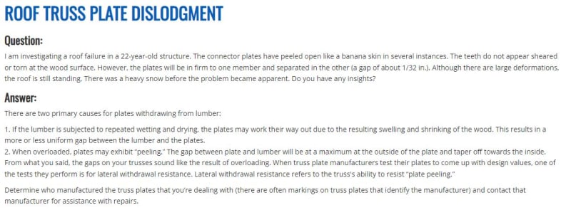
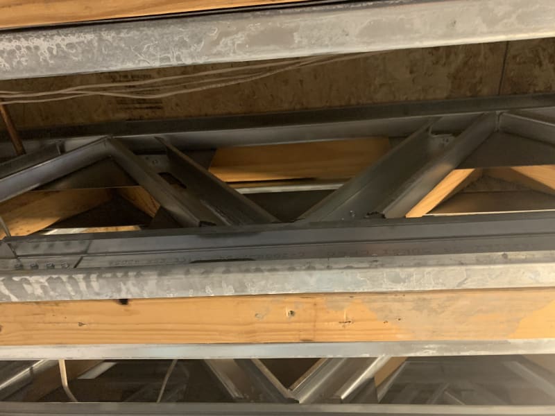
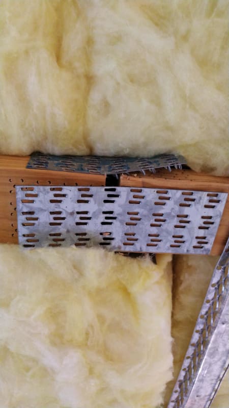
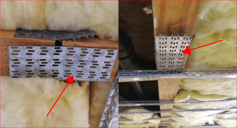
These are images wood floor trusses, taken from the floor looking up. The building is used as an assisted living facility. I cannot see how the floor would have been overloaded given the use of the facility.

Any thoughts on what could be going on? The facility was constructed in 1996. The floor live load for this area was listed at 100 psf.

I am making an additional visit to the site tomorrow to see if I can figure out what is happening. Apparently as the contractor doing cosmetic renovations removes areas of ceilings, he is finding this condition frequently.

Thanks in advance for any insight.
 
Replies continue below

Recommended for you

bones206, the original comment about a communal area was based upon information I was provided with. Once I got to the site myself, I was able to verify the actual use of the floor above. I was also able to validate the assumed load with the original drawings.

At this point, our plan is to site build light gauge steel trusses on each side of each existing truss. With all of the duct work, sprinkler lines, plumbing, and electrical running in the web space, we don't have too many options.

The contractor opened this area due to cracks in the ceiling. Since the entire structure is being renovated, we are going to implement a plan of inspection throughout the entire facility. Hopefully we are isolated in this area, but I am not overly optimistic.

WARose, I am with you, after spending the day design light gauge connections for this application, I cannot see how those truss plates work. The number of screws required is quite large.
 
Am I misinterpreting the OP photos? They are repeated below. I think these are two photos, side by side, each showing the bottom chord of a truss, meaning the plates are in tension. The plates marked with a red arrow cannot be installed in the usual manner, i.e. with a hydraulic press, so they would have to be installed with a hammer, which would not provide a satisfactory grip between plate and bottom chord.

The plates in the op appear to be different than the latest photos.

Capture_rjfhjh.png


BA
 
Looking at the jointing, it could be that the entire framing might be suspect. I've never seen trusses with 'square' cut web members.

Rather than think climate change and the corona virus as science, think of it as the wrath of God. Feel any better?

-Dik
 

I would not be looking at light gauge... I'd be looking at plywood, nails/screws, and adhesives.

Rather than think climate change and the corona virus as science, think of it as the wrath of God. Feel any better?

-Dik
 

I love to see 'about' and 'exact' in the same sentence... (slow day)...[ponder]

Rather than think climate change and the corona virus as science, think of it as the wrath of God. Feel any better?

-Dik
 
[blue](OHIOMatt)[/blue]

WARose, I am with you, after spending the day design light gauge connections for this application, I cannot see how those truss plates work. The number of screws required is quite large.

Yep. Some years ago (no "exact" estimate for the date this time [smile]) I tried to get someone [like Simpson] who makes them to tell me what they were good for in terms of loads (i.e. without any framing nails, etc; just the spikes). And they refused to do so.

 
Not sure about the edition from 25 years ago, but TPI 1-2014 is pretty informative. I haven't been through it in enough detail to handle OHIOMatt's situation, but I did review it enough to make me feel okay about metal plate connected trusses. know it isn't just a bunch of voodoo magic. Somebody did some actual testing to figure this out, and there's a way to calculate it.

ANSI/TPI 1-2014
 
I believe the plates are never tensión elements. So they should probably all be replaced with bolted members or steel plates.
The plates are neither continuity plates.
The plates are assembly plates, and they also should be nailed.
You would probably find that the strut and chord members should be doubled, thus nails can penetrate the withdrawal distance requirement.
Nice photos! Appreciative of the shared discussion.
2cents
 
Very interesting (and concerning) condition OM. I'll be curious to hear the final resolution.

A few thoughts:

Looking at span, depth of truss and loading, it looks like member forces will be very high.
While I don't believe that in reality we ever see the full design floor loads, they are there for (good) reasons.
With that said, overload does seem to be a possible issue. I assume you will be doing some calcs for that to see what the actual member forces are.

I agree with others - that joinery looks horrible. I WOMDER if they were not actually factory made.

I also agree that the plates look more like mishandling than over-laod but that does not explain the apparent timing of the drywall distress.
I would have expected problems before now if mis-handling was the cause of the distress.
Was thre mechanical work done in the area of the distress? Just wondering if something or someone disturbed the trusses recently.

My experience is that press plates don't "work" by conventional design calcs but rather they "work" because of testing and QC in fabrication.

fugeeo - Except for the poor joinery and possibly the fabrication (in this case) press plates are very standard for this application.

phamENG is right - It seems like magic but there's a bunch of testing and procedure/controls behind truss "design".

 
HouseBoy said:
I agree with others - that joinery looks horrible. I WONDER if they were not actually factory made.

Yes, I wonder about that too. Some of the plates could not have been installed using a hydraulic press. Perhaps a hydraulic press was not used on any of the joints. A little detective work may be necessary.

BA
 
a swing press... aka hammer.

Rather than think climate change and the corona virus as science, think of it as the wrath of God. Feel any better?

-Dik
 
It seems that this is not an uncommon problem. Apparently the industry is aware of it, but cannot predict when it will happen. When the trusses were originally built, the joints shown in the photos were acceptable to the plate manufacturer. We are finding the problem extensively throughout the building. While we still don't know what caused it, we have been able to rule out the following:

[ul]Over Loading
Mishandling during erection
improper pressing of the plates
Non-approved fabricator
[/ul]

The suspect areas of floor have been shored. We have designed light gauge trusses to be sistered to the existing (we are actually placing one on each side). While we had hoped to just repair the joints, we found that the stress redistribution caused by the failed plates had actually broken quite a few internal members. It is a tedious and expensive process. The photo below shows the finished product:

Photo_Sep_02_9_08_06_AM_f8t8bo.jpg
 
phamENG just did, but they were roof trusses. We do have a few reports here from time to time, but most are usually attributed to overloading.
 
Status
Not open for further replies.
Back
Top