Continue to Site

Eng-Tips is the largest engineering community on the Internet

Intelligent Work Forums for Engineering Professionals

  • Congratulations SSS148 on being selected by the Eng-Tips community for having the most helpful posts in the forums last week. Way to Go!

Wood Framed Parapet Wall at Balcony 2

Status
Not open for further replies.

JungleJoe

Structural
Jun 25, 2021
35
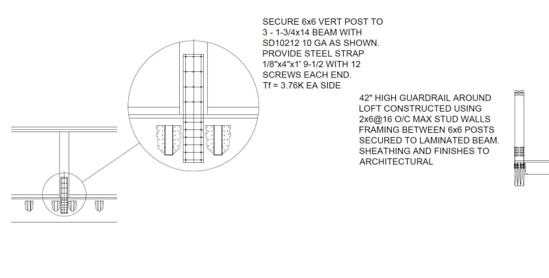
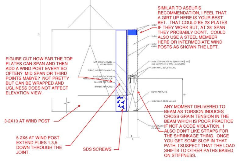
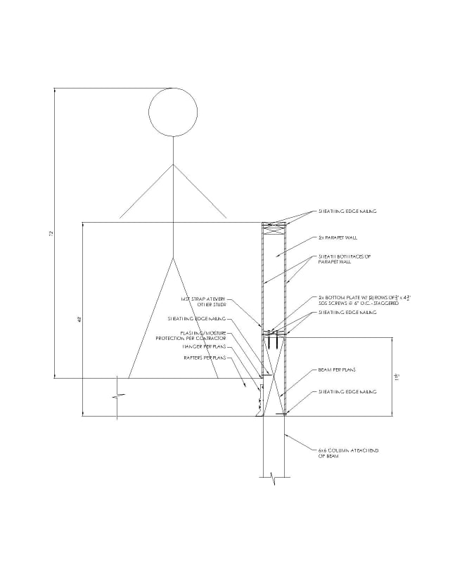
Hi everyone, thanks for reading. I am working on a residential project with a southwest-style flat roof with parapets. One area of the roof is going to be usable space with stairs going up to it on the exterior of the home. Below this area is a deck that you can walk out onto from the kitchen. I am working up a detail for the parapet wall at the usable roof space above. The owner does not want to use kickers to support the parapet for obvious reasons. Balloon framing the parapet is also not an option since it is an open deck below. The "floor" that you walk on will be 2x10's that hang into a beam that spans to a 6x6 column at each end. I want to see what your opinions are on this detail I'm working on. I am thinking that with the sheathing applied to both faces of the parapet wall and the SDS screws into the beam that this wall will be quite sturdy. There is no snow load to worry about where this home is being built. One thought I had (labeled on the drawing) for some peace of mind was to add an MST strap on the inside face of every other parapet stud, attaching the stud to the beam. I'd love to hear your thoughts. The total height from the bottom of the beam to the top of the parapet wall is to be 48". I drew a 6' tall person on the drawing for scale. The beam itself is 19.5" tall. Thanks!

Here's the drawing. I have also put a link to the drawing at the bottom of the post.

Parapet_jy14ua.jpg
 
Replies continue below

Recommended for you

I would start with calculating the moment and then strap force based on eccentricity of the stud to figure out what strap to use and the spacing. I would then look at if there was any torsion issues with the beam. I have seen this done for small parapets, however for parapets of considerable height it's much more difficult, but not impossible to calc out. While I haven't calc'd your scenario, I would expect you to have 700 to 1000 lbs force at the strap tension or compression when considering components and cladding wind loading on a parapet. I believe a MST strap requires a minimum of two studs or a 3x member, you will probably want more of a MSTA or LSTA strap to fit a single stud. I would also suggest looking at using "A" clips at the stud to plate for shear forces.

I'm not sure if the sheathing would have sufficient capacity to resist this moment, it would need to be checked.

Another option could be to use the columns to cantilever up past the beam and have a high beam spanning between columns supporting a wall between the high and low beams, however with this option the beam supporting the roof/balcony will need concealed face mount hangers, similar to an HUC, and these may not have sufficient capacity for your loading.
 
This was from a commercial (church) project I helped my classmate with several years back. There's a lot to making sure things are connected against substantial guardrail forces, in particular with wood.

Clipboard01_ywpo93.jpg


Rather than think climate change and the corona virus as science, think of it as the wrath of God. Feel any better?

-Dik
 
You can definitely detail it such that it calcs out, but any I think any strap solution will inevitably loosen as the wood shrinks. I have tried your exact method of sheathing a knee wall for a stairwell with 3/4" osb. It did not stiffen the kneewall adequately. It would have been safe, but if you grabbed it, it moved and I'm sure it would have continued to loosen over time.

You could also try threaded rods on alternating sides of the wall cavity that bolt through the edge beam. I have used that for a parapet before. You still could have shrinkage though.
 
Maybe you could add some 2x strongbacks flatwise to create T-shaped studs at some interval. Run the strongbacks down the full 48” height and fasten to the inside face of the beam. The overturning moment can be transferred from the T shapes into the joists using some kind of blocking detail that create a horizontal lever arm. The downside to this detail is it makes the parapet 1.5” thicker.
 
Another issue with your detail is that the tension side that really matters (the one that keeps stick man from falling off the roof) only connects halfway down the beam. That means that the torsion you're putting into the beam isn't equally applied and I think you'll end up with some tension across the grain, which is often frowned upon.

What is the span between the posts below? Is there an option to bring those posts up to the top of the parapet with the beam framing into the sides on a concealed flange beam hanger or similar connection? Then you could make the top plate on the parapet wall a bit more substantial to span between them. Remember, residential guardrails don't have a 50plf requirement in the IRC - just a 200lb anywhere requirement.
 
In may codes, the direction of the loading is not only outwards.

Rather than think climate change and the corona virus as science, think of it as the wrath of God. Feel any better?

-Dik
 
dik - I agree and US codes are no exception ("applied in any direction"), but outwards is typically the one with the most severe consequences. There's also an effort underway to change the IRC so it's 200lbs outward or downward, and 50lbs inward or upward. Most of the details out there for wood deck rails are only tested for the outward application of load. In this case, it looks like outward is the weakest direction.
 
I've occasionally stretched the loading... not often, though.

Rather than think climate change and the corona virus as science, think of it as the wrath of God. Feel any better?

-Dik
 
phamENG said:
Another issue with your detail is that the tension side that really matters (the one that keeps stick man from falling off the roof) only connects halfway down the beam.

Since the rafters are spaced at 16" I was thinking that I could position the straps between rafters so they could run all the way down the side of the beam. SJBombero mentioned that the straps would loosen as the wood shrinks, but I'm not sure if that's something I should be overly concerned about
 
Yes, yes it should be. Wood shrinkage is a well known and well documented phenomenon. One of my early assignments was helping my boss defend another engineer in court when wood shrinkage sprung the straps on the side of the building and the cladding fell off onto the cars below. We didn't win. The engineer we were helping defend had to pay for the damage to the building and vehicles. Because it was a known and predictable issue.

Your situation is a little different, but you still know it can and will occur and you should account for it in your design.

If you can mis-align the joists and studs, then you may be able to make it work.
 
Thanks phamENG. I guess my struggle with what SJBombero and you are saying is that if the straps will indeed loosen over time then why would we ever use straps at all in any application? If the wood is going to shrink then it'll shrink, and there's nothing we can do to make that strap stay taut like we want it to (unless I use engineered lumber?). I guess I should be looking at a solution other than straps, although you mention that I could still maybe make it work. However, if the straps are prone to loosening then I don't see how a solution with straps could be made to work. It looks like dik's detail above uses a strap.

The beam spans 28' so it's quite long. The reactions at each end are around 4600 lb. so there are some concealed hangers that could carry that.
 
and it works... even with straps, the moment capacity is retained... there can be an 'air gap'.

Rather than think climate change and the corona virus as science, think of it as the wrath of God. Feel any better?

-Dik
 
I have used, and continue to use, details similar to OP's. So nobody should interpret my recommendations here as being "holier than thou". One of the nice features of this forum is that it's a safe space (relatively) where we can dispense with the kid gloves and hold others to standards that we do not necessarily meet ourselves.

c01_dym2rp.png
 
JungleJoe:
Why not make the beam a stl. bm. which could be much less than 19.5” deep and around 5.5” wide. Weld 5 canti. stl. posts atop the beam, with screws upwards through welded cap pls. on the posts for the top railing, thus 4 - 7’ top railing spans, likely o.k. with a double 2x6 top railing. One top pl. is 7’, 14’ & 7’ lengths, and the other is 14’ & 14’ lengths. Put 2x6 wooden pls. top and bot. on the stl. bm. and otherwise pack it out for the 2x10 jsts. and hangers on one side and for the wall sheathing and siding on the other. The 2x10 jsts. and hangers do not offer much support for the railing canti. moment, (stl, bm. torsion) so double the 2x10 jsts. at each stl. post and tie the whole stl. bm. back into those doubled fl. jsts. and the fl. diaphragm, with hardware like you would for a wooden deck structure. Then infill the parapet wall with wood framing at 16” o/c.
 
I think that KneeWall connector has to be anchored down to concrete.
 
That knee wall tech spec is for anchoring to concrete, but I would think one could design a wood fastener to replace the concrete anchor.
 
Would it be code compliant though? These products have specific limits of applicability, ESR reports etc.
 
We in Canada seem to have a little more leeway in the code comlpliance departement which tends to spur our creativity aome. Up here in Alberta, we don't even submit calculations.
 
Status
Not open for further replies.

Part and Inventory Search

Sponsor