Continue to Site

Eng-Tips is the largest engineering community on the Internet

Intelligent Work Forums for Engineering Professionals

  • Congratulations SSS148 on being selected by the Eng-Tips community for having the most helpful posts in the forums last week. Way to Go!

Wood light pole base

Status
Not open for further replies.

braves25

Structural
Jan 2, 2004
64
Hello,

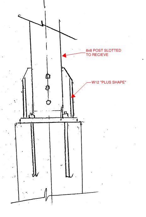
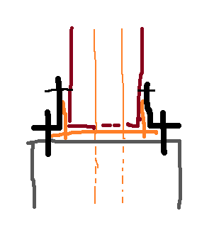
Has anyone designed a light pole base for a wood poll? I have a 14' wood post (8x8) with a single fixture a the top. The owner wants a concrete footing (drilled pier or square, I don't think that matters to them) and a fabricated steel base connection, that is connected to the wood post with bolts. Anyone had success with this type of connection. Critical areas to consider in the connection design? Thank you and have a great day.
 
Replies continue below

Recommended for you

More smaller fasteners will perform better long run. The wood will tend to shrink away from both the steel saddle, and the fasteners, and will then be a little wobbly. There's not a good way around it, the demand on the connection can't be enormous, does something like the simpson strong-tie MPBZ work for you?
 
The owner wants a fabricated connection to make the base look more attractive.
 
I would model it after their intent. They've got testing backing up what they've done. There's a reason that for all of their other post bases they have warnings, not designed for cantilever poles.

Like I said, it will be loose if they only want to use a couple of bolts. Yes, it won't fall over, but it will be wobbly after a few years as the wood shrinks.
 
Sounds like a round square HSS sleeve that the wood pole will fit inside of welded to a base plate may work. I would have a hole (large enough it won't easily get plugged) in the base plate to allow water to drain. I would also have a few through bolts to prevent the pole from lifting out of the sleeve.
 
Given that the post is expected to shrink, would a base with separate plates up each side of the post be better than a box section, so that the fasteners at the top of the base could be retightened later, after the timber shrinks? Possibly with a pin (or pipe) at the bottom matching a hole in the end of the timber to keep the bottom centered?

What I've seen most often done in those situations is just embedding the post directly in the concrete. Keeping a seal around the base can be a challenge, though.

Rod Smith, P.E., The artist formerly known as HotRod10
 
1) I would normally do the embedded solution that BridgeSmith described.

2) This may well be one of those cases where advising your client well will mean telling them that they don't really want what they think they want.

3) The scale of a light pole for a connection like this unnerves me a bit. I've taken liberties with these connections for stupid stuff like small signs and garbage enclosures. A 30' tall light pole that might ice up at etc, and possibly fall on cars, is another kettle of fish in my opinion. How tall will the poles be? Will there be a metal mast arm out to the lamp?

4) I'm okay with a vertical fin plate slotted into the pole and bolted. However, that means that you're relying on the fin plate in weak axis bending in one direction which will seriously limit capacity.

5) Like BridgeSmith's four plate suggestions, I've seen details where this was done with a pair of vertical angles wrapping the corners of the pole and bolted in as a means to provide a way to tighten up shrinkage related slop. Frankly, I think this is pretty ugly though.

6) I might be willing to bend a bit if the client could point to similar detailing, already in place, that had a satisfactory performance history.

 
Any chance you can just run a steel pole up the middle and make the wood and base connection all architectural?
 
Many moons ago I was involved in one of these, we actually had a row of them. We made "H" sections where the center was not welded to the sides, there was actually a small gap. So effectively we had fin plate up the center of the post, and side plates to brace in the other direction. We bolted all of it with carriage bolts and then trimmed the excess bolt off and put domed metal caps over the bolts. It looked like it was riveted in place but it could still be snugged up by removing the caps. We went back at the end of the next summer and re-tightened it. After they were fabed they were galvanized. And the concrete piers came 6-9" out of the ground to try and keep things dry. I don't recall how they were anchored to the pier. Last I saw they were still there after about 35 years.

= = = = = = = = = = = = = = = = = = = =
P.E. Metallurgy
 
KootK said:
A 30' tall light pole that might ice up at etc, and possibly fall on cars, is another kettle of fish in my opinion. How tall will the poles be?

The OP stated that it was only 14' tall.


KootK said:
I'm okay with a vertical fin plate slotted into the pole and bolted. However, that means that you're relying on the fin plate in weak axis bending in one direction which will seriously limit capacity.

Why not take this a step further and have a vertical "Plus" Shape to avoid the weak axis bending.
 
dauwerda said:
Why not take this a step further and have a vertical "Plus" Shape to avoid the weak axis bending.

Love it. But then the question become what is that "plus" shape, how does it look, and how does it allow the connection to be drawn in for shrinkage. Obviously, Ed's got on answer to that. What have you got in mind?
 
No doubt I am completely fooling myself in thinking that anyone might find this sufficiently attractive.

c01_egmx9k.jpg
 
The problem with tightening bolts in the cruciform configuration would be similar to that of the I that Ed suggested when you look at the bolts going through the "web" of the I. If we assume 6% average shrinkage perpendicular to the grain (radial and tangential) over a 30% moisture swing, and further assume that we're going from 19% as delivered lumber to a 12% dry equilibrium MC in dry months, then a 3.5" block would shrink about 0.05" (figure a 1/4" steel plate and you have 4 3.5" blocks with .25" gap). So we end up with a total of about 0.1" of slop in the joint. Half of that is taken up by the bolts being snugged up to the surface of the wood, the other 0.05" by bending the wood to contact the steel plate. Might be a problem if your connections only an inch long, but if you run your cruciform up, say 8" into the wood, then you're looking at rotation in the wood of about 0.36o. Probably not enough to be worried about.
 
Oh, and don't forget stand-off tabs to keep the wood up off of the concrete/steel so it isn't sitting in or wicking up water.
 
KootK said:
No doubt I am completely fooling myself in thinking that anyone might find this sufficiently attractive.

I don't know - use it the parking lot of a structural engineering office and I'll bet everyone would be pretty pleased.
 
Ah... plus = cruciform. Now I get it. I don't love it though. I think that the post would be too chewed up at the bottom by the time that you got all that slotted in.
 
Not if it's done right. Assuming 1/4" plate works, you essentially have four 4x4's within the connection.

You could also go so far as to reinforce the connection region with a) a thin steel plate or sheet screwed into the post or b)2x12's mitered around the corners and screwed into the post.
 
Can you put the post into an HSS sleeve that is welded to the base plate? KottK's fins look nice but I forsee someone walking into them or tripping over them.
 
phamENG said:
Not if it's done right. Assuming 1/4" plate works, you essentially have four 4x4's within the connection.

I don't buy it. By the time that you get two columns of bolts flying through that, I think that it'll be a dog's breakfast of beat up timber. And each one of those 4x4's needs to be an upside down cantilever of sorts.
 
Anybody think this might work - core and insert a fully grouted pipe into the pole, and embed in the concrete pier.

Post_fbptbx.png
 
Status
Not open for further replies.

Part and Inventory Search

Sponsor