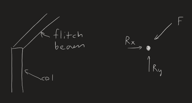
XR250 - Regarding "The ridge is supported vertically by a bent flitch or I-beam at the gable end - thus eliminating thrust. Similar to this..", I'm not having any difficulty understanding what you propose. It is a very common approach. In fact, I've done this several times. However, once I modeled this framing in 3D, I was really surprised about what is really going on. Consider this: visualize the ridge beam deflecting (which it will). What happens to the roof rafters? Do they compress axially to compensate? They do not because the axial stiffness of the rafters is greater than the flexural stiffness of the ridge beam, even if you use a GINORMOUS ridge beam. The ridge is either going to be supported by the rafters, transferring the thrust to the adjacent structures, or the walls are going to bow outward, resisted only by the flexural/axial capacity of the top plate (yikes!).
Milkshakelake - When you are visualizing the plywood sheathing taking flexural loads, please consider that the boundaries of the individual plates (ridges, hips, etc.) are continuous pins (think piano hinge) and not able to transfer moment.
My recommendation still stands, and I think, with some assumptions, the analysis and detailing is not that onerous.
1. Use a 2x ridge board. Anything more is a waste of lumber.
2. Analyze the rafters as a pinned-pinned truss.
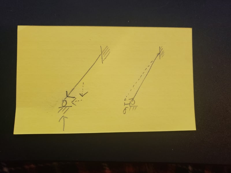
3. Apply the horizontal and vertical reactions to the adjacent structures. Note that the thrust load in reality is not linear, but parabolic, with zero thrust at the ends and maximum at the middle. To convert to an equivalent uniform load, use 2/3 of the maximum load, but design the adjacent rafters for the maximum load.
4. Connect the rafters to the adjacent structure with a sleeper and blocking between the supporting rafters.
5. Consider this load in addition to the RLL+DL when designing the rafters on the adjacent structures.
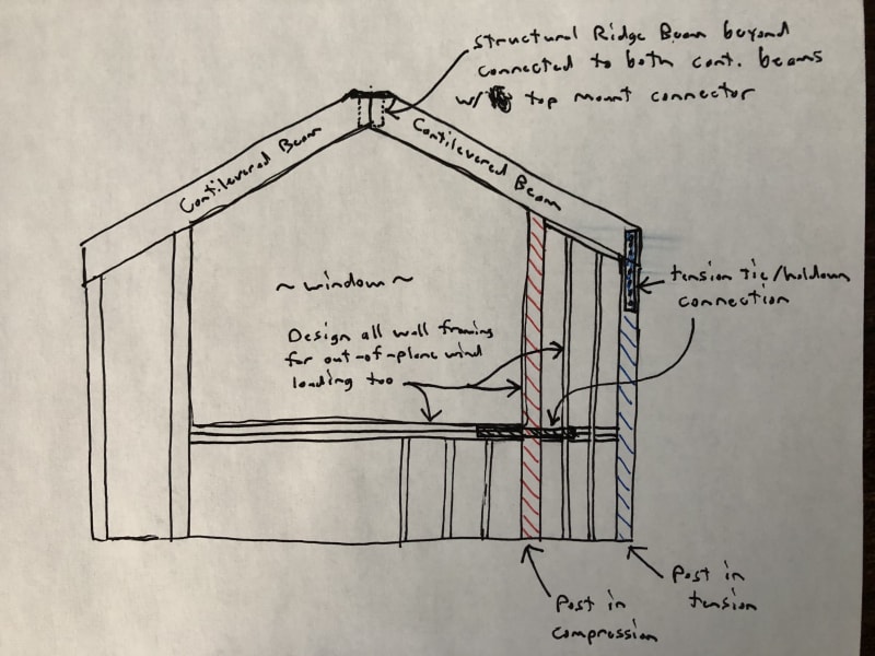
6. Take the lateral load out in shear resisting elements of the adjacent structures, shear walls for the element on the right of the entry, cantilevered columns on the structure to the left of the entry. Depending on the load, you might be able to get away with wood posts and Simpson MPBs. Be careful of the load factors. The capacities for the MPs are based on 1.6 load factors. Also be mindful of the deflection. This is a long term load and wood is subject to creep. This element is visually exposed, so any significant deflection will not make you look like a hero in a couple of years. HSS columns, wrapped with wood are relatively cheap. You probably can get away with a 2 bolt base plate as it will weigh less than 300 pounds. The forces shouldn't be huge. Use flagpole footings restrained at the top by a tie beam (footing).
7. You're done! You had some fun! You don't have to think about this ever again!