Continue to Site

Eng-Tips is the largest engineering community on the Internet

Intelligent Work Forums for Engineering Professionals

  • Congratulations MintJulep on being selected by the Eng-Tips community for having the most helpful posts in the forums last week. Way to Go!

Wood open roof 2

Status
Not open for further replies.

milkshakelake

Structural
Jul 15, 2013
1,130
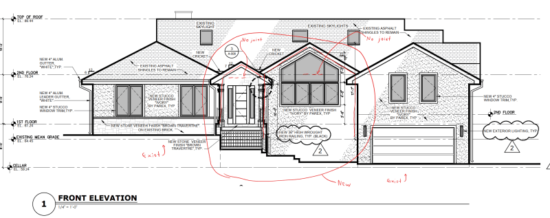
Client wants an open gable roof. I don't like to do it generally because of lateral thrust; I'm more comfortable with having horizontal attic joists. Are there any references for how to design something like this? I was considering having some horizontal timber beams at like 8'-0" on center to deal with the thrust, beyond the window so the structure wouldn't obscure the facade.

Screenshot_2023-11-17_103647_fe1eka.png
 
Replies continue below

Recommended for you

XR250 said:
What is a "PMB"

I'm assuming SE2607 is referring to the MPBZ, moment post base. I've tried to use those before, and they only thing I can make them work on are the sorts of structures they use in their marketing brochures: pergolas and small outdoor structures. They just don't do all that much.

SE2607 said:
O.K. I got it. Ignore boundary conditions and deformations

Nobody said to ignore them. But it feels like your analysis, unless it's going full folded plate (something a bit like this), is ignoring boundary conditions that are important to your assumption that the thrust can be transferred into an adjacent, non horizontal diaphragm set in a different plane.

I do find your statement that a ridge beam doesn't do anything to eliminate thrust interesting. You're literally taking on the whole of practicing residential engineers in North America with that statement (and probably more than that, but I'm not familiar with typical framing practices in other parts of the world). Sure, we need a little mix-up and disruption now and again, but is that where we need it? In some cases, I'd agree with you that we do. Mostly because our codified serviceability limits don't adequately capture issues that can come from ridge beam construction. At t=0, I agree that the ridge beam has not done anything to eliminate thrust from the rafters. At t=0.1(ish), though, the ridge has deflected, the rafters haven't really shortened all that much at all, the walls or beams supporting have deflected out slightly, and the entire thing is in equilibrium in a stable condition with essentially no thrust at the base. In reasonably sized ridge beams, none of this is a problem. If you're trying to span 40ft and end up with 4" of deflection (L/1200, which "meets code"), a 12:12 roof would push the wall out 4" and probably destabilize it. So yeah...that's bad.

But, I'd say most of these things should be considered qualitatively first and then address the details quantitatively. You have to understand the load paths to pick the one that makes the most sense for both safety and the practicality of design.
 
There's a building down the road from me that was built in the 1960s. The studs were connected to the rafters with large plywood gussets. (No top plates on the wall) And the peak of the rafters were also connected with large plywood gussets. It was built with a design for agricultural buildings, and was designed at Purdue University in Indiana.

The actual design of the structure is beyond me. I'm just tossing out a possible solution.
 
phamENG - Thanks for the correction on the MPBZ.

What you are saying is exactly what I'm recommending; consider deformations when developing the mathematical model. Unfortunately, I believe most engineers don't think about deflections enough. Frankly, I think too many engineers are just lazy, using the excuse "I need to make money" to put the time into considering deformations. BTW, Most engineers would allow a ridge beam deflection of L/240 or L/180 depending on the loading. Bowed walls, while structurally acceptable to a point, are not visibly attractive, especially when you consider the creep effects of wood framing under continuous loading (unlike transient loading such as wind or earthquake). FWIW, when I was learning to use RISA 3D, I was modeling a structure similar to this (free standing, with no adjacent diaphragms). It had a gable at one end and a hip at the other. At the intersection of the hips and ridge, I modeled an inverted chevron HSS "bent" beam. It was pretty amazing how little the stiffness of the ridge beam made on the results. It had pretty stiff rafters (2x10s to accommodate R-30). It had to get HUGE to have any significant effect. Stiffness was also the driver of the HSS chevron.

With regards to your comment on "taking on the whole of practicing residential engineers", that's kind of my point. I've been a "wood butcher" for 30+ years and I still haven't learned everything yet. We all do things for convenience. To make a buck. Nothing is wrong with that. But, what I'm suggesting, is to at least have a defensible position if/when something goes wrong. To your point, just think about deflections.
</rant>
 
What I ended up doing is a Frankenstein monster of sorts, incorporating a bunch of different ideas here and making it probably more redundant than it needs to be, but it works and is constructible. I ended up not using any FEM because that would kill the client with billing. Besides, I'm not 100% sure that the values I use for stiffness would be entirely accurate because of nail slip, and it would be a deep rabbit hole to fall into. I think the arrangement I have (engaging adjacent diaphragms, using some cantilever column action, engaging shear walls, using a ridge beam, holddown, etc) is good enough and not exorbitantly costly or using too many details. It's maybe a bit over-engineered, but nobody likes their building to deflect and it's defensible so it should be okay. I ran some quick hand calcs to make sure the members are sized properly and didn't do a "scientific" analysis on it.

About the controversy at hand, I think it comes down to how comfortable you are with the approach. Some engineers might eschew rigorous analysis because they simply don't know any better, but I know XR250 is not one of them. I think it's okay to rely on a combination of fundamental principles and experience sometimes. And with wood (and unreinforced masonry) in particular, there is a point where adding more steps to the analysis introduces more variables to the point where I wouldn't know what's real or not. It's like trying to hunt a bird but your rifle isn't accurate, there's wind, and it's flying in an unpredictable path. That's how I feel about how wood diaphragms and load paths work. As long as I switch to a shotgun and point in the right direction, I think it should be okay. It's distinctly different from how I feel about concrete and steel. Steel/concrete have some wishy-washiness as well, but at least we don't have sloped diaphragms, top plates, bottom plates, rim boards, hold-downs etc.

I did an FEM model of a similar bent beam in the past (didn't model rafters and ridge beam though) and I know that the deflections are much more than what one might intuitively guess. The deformation due to flexure is an order of magnitude higher than axial deformation, similar to steel moment frames versus braced frames. So the deflections start throwing loads into stiffer members that might not be accounted for, like an adjacent diaphragm. I think addressing this is enough, and ignoring it is not good. But doing an analysis on this is overkill. So I'm leaning to XR250's side, but I totally understand what SE is saying. (How's that for being diplomatic?)
 
I have the benefit that others may not of a huge amount of field experience. I have been doing this since 1991 and have been to well over 5,000 houses. As such, I have a good feel for what works and what doesn't and where to spend my time effectively on design. I can't imagine resorting to a 3D model for anything in light frame construction. Trying to account for all the different stiffnesses in the elements is likely to be futile.I use a 30 year old, 2D frame program on my Mac and it serves me well. I can knock out a bent flitch design in 5 minutes or less.
The fact is, we are not building clocks here. Light frame construction has a huge amount of redundancy which makes it a pretty safe thing to design, You can f it up pretty badly and it will still likely work fine. I have seen countless vaulted ceilings with no structural ridge on 30 year old houses with only minor bowing of the exterior walls and no obvious distress to the finishes.
Trying to determine if the deflection of my structural ridge will cause sheetrock distress in the adjoining room because it is stiffer seems absurd to me. I design most elements to L/600 which I feel keeps me out of trouble. Let's face it, other than possibly roof loads, a house is never, ever going to see even close to full design loads.


In reality a contractor could build this house without any of the structural elements talked about here and there's a pretty good chance that there would be no issues. But if there were issues, where would we find them? Here's how I would approach it:

- Assuming I'm working in a snowy area, you'd get some noticeable ridge deflection during those bad snowstorms. Okay, let's add a ridge beam then since we don't have rafter ties/ ceiling joists.

- Are the side walls going to thrust outward? Unlikely, since we have adjacent structures to brace them in addition to us using a ridge beam.

- The end wall is important. It has to support our ridge beam and also be stiff enough for those windy days. Let's create an HSS frame (or cranked flitch) to support the ridge. Then let's make sure our 2x6 wall studs can handle the wind. Double them up if needed. No one who spends a ton of $$ on a big window like this wants that thing moving in the breeze.

Obviously the easiest thing is to change the window layout to accommodate some hidden structure, but if they really want the big window they are going to have to deal with some additional steel in that end wall. Nothing crazy though. Pretty quick 2D analysis and design. Plus around here it would only take a week or so to get a few HSS tubes on site.
 
I realize I may have come off as an academic with little "real world" experience in my original post on this topic. Nothing could be further from the truth. I started my own practice in 1987 after working for others for 10 years. Originally, my clients were contractors doing residential remodeling. Thank GOD I didn't keep a time card then! I had to shave every nail and foot of shear wall out of all of my designs to keep my customers. I eventually got into commercial work, hired a staff and realized that I wasn't happy managing people and creating a workflow geared for the "lowest common denominator". I eventually let every one go and returned to my roots. For about the last 15 years, I've returned to residential remodeling. I've been very fortunate to find a niche in the high end market of Southern California where I could produce work I am proud of. I have NO IDEA how many structures I've designed in my career. LOTS!

A very common project I have is to remove the flat ceiling of a residence and convert it into a vaulted ceiling. I would add ridge and hip beams below the existing ridge/hip boards, and add an inverted HSS chevron where the hips meet the ridge. About a year ago, I got a license for RISA 3D. I always wondered about deflections in these kinds of structures. So, while I was learning RISA 3D, I built a representative model. I really was surprised by the results. Even when I don't use RISA on a project, I am much more careful about deflections and stiffnesses of members. I believe that's a good, not bad thing. I've gotten efficient enough with RISA, where I can use it productively (i.e., faster than doing it by hand) about every third project.

I am certainly not suggesting that everyone/anyone NEEDS to use 3D software to design a house. That's ludicrous. However, with the exception of simple beams, some kind of analysis software, even 30 year old 2D software, makes it possible to look at deflections. From a 2D analysis, most of us can extrapolate to 3D most of the time. Even the "bowing wall" problem can be solved in 2D. The wall has maximum bow at the midspan of the ridge and has zero bow at the ends. Once that is known, it is pretty easy, either by quantifying or qualifying, to determine the overall impact on the structure, including the secondary stresses in the top plate, regardless if one determines those stresses are from flexure or catenary action. If the wall bows, there are stresses in the top plate...because it gets longer!

Most of us know that a lot of the stuff in the conventional framing provisions don't "calc out". Is that a reason to stick our heads in the sand or at least pause to see if we should do something different, even at the risk of being accused of "over engineering"?

Hopefully, what I've achieved here is to get engineers to think about deformations, particularly with wood structures. If I've offended anyone, it was purely unintentional.
 
Status
Not open for further replies.

Part and Inventory Search

Sponsor