Continue to Site

Eng-Tips is the largest engineering community on the Internet

Intelligent Work Forums for Engineering Professionals

  • Congratulations waross on being selected by the Eng-Tips community for having the most helpful posts in the forums last week. Way to Go!

Wood Stud Capacity - Weak Axis Lateral Support 1

Status
Not open for further replies.

codySTR

Structural
Dec 28, 2017
32
I'm creating a spreadsheet to compare wood stud capacities (based on length, width/breadth, bracing, wood species/grade, etc., etc.). I'm questioning my assumptions for the lateral bracing of the stud. Specifically, I'm questioning the correct application of the NDS 2015 provision A.11.3 (appendix), which states:

"When stud walls in light frame construction are adequately sheathed on at least one side, the depth, rather than the breadth of the stud, shall be permitted to be taken as the least dimension in calculating the le/d ratio. The sheathing shall be shown by experience to provide lateral support and shall be adequately fastened." (note: The main body NDS 2015 provision 3.6.7 pushed me to look at the Appendix provision A.11.3 quoted here)

Generally, if I'm considering a load bearing wood stud wall with at least one side sheathed, I use the full stud height (from top of sill plate to bottom of top plate) for the strong axis length and the center-to-center distance of blocking as the weak axis unbraced length. Based on the quoted NDS provision, would it be acceptable to use the sheathing nail spacing (I'd use the field-nailing nail spacing for general use) as the weak axis unbraced length and use the member depth (i.e. 5.5" for a 2x6 stud) as the "d" value in the le/d ratio?

Edit: I want to add a quick comparison of stud capacities. By my math, using my "general" bracing assumptions (full length for strong axis, 4'-0" unbraced length for weak axis due to blocking at 48" o.c.), a #1 2x6 Douglas-Fir Larch stud has an axial capacity of 3.8 kips. Applying the A.11.3 provision assuming the weak axis unbraced length is kept at 48" (i.e. I'm not assuming the field nailing spacing applies), the same stud now has 5.3 kips capacity. That's a nearly 40% increase in capacity.
 
Replies continue below

Recommended for you

cody:
so with python-xy installed you can double click any of the .py files to run the scripts, if the file name has "gui" in it's name you'll get a graphical interface otherwise if it doesn't take any user inputs a command prompt window will open and then close for these ones open them in Spyder, see attached screenshot, and you can run them and see realtime variable results.

I relied a lot on youtube/google but got started with two books Automate the Boring the Stuff with Python and Python for Kids (despite the name is a excellent beginner book and even gets into some GUI stuff)

Quick animated gif showing basic spyder use: gif
(there's a portion that gets cut off in the gif, I am clicking on the quit option in the context menu that pops up)

Capture_iok2xw.png


Open Source Structural Applications:
 
To open it via command prompt in Windows:

Open start menu
Enter the following:
Code:
cmd

In the command prompt type the following:
Code:
cd C:\Python\[i]folder where you put the python scripts[/i]
For me I would type; cd C:\Python\Scripts

Then type:
Code:
python wood_stud_wall_gui.py

Ian Riley, PE, SE
Professional Engineer (ME, NH, VT, CT, MA, FL) Structural Engineer (IL)
American Concrete Industries
 
Celt and TME:

Thanks for your responses! I'm hoping I can learn a lot more about this python stuff in the future; I really enjoyed some short spurts of programming for school-related projects and some extra-curriculars.

For now, I'd really like to simply open the program and poke around a little bit and compare with my own work. Unfortunately, I'm still struggling simply to open this darn thing. I have the spyder environment open, but I'm not sure where to go next. Do I copy the code and paste it into the editor, save as a .py file, and hit run? Or should I be able to download your github file and double-click it? TME's response seems to suggest to me that I should be able to download the github file, save it somewhere, and use the windows command prompt to run the program/script... but I can't find a "download" button for your github file.
 
Celt:

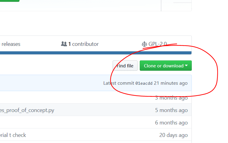
I finally got it up and running. Thanks for your help! TME's post made me realize that I needed to create a Github account first before I could see/use the download button he pointed out.

First thoughts about your program:
1) Wow. Good job. I wish I could make such a robust tool.
2) I realized that the user is required to apply a >0.0 value for the lateral pressure. While this requirement isn't all that bad, I was getting stuck because I was trying to use your program for pure axial capacity and it took me a minute to understand the above requirement.
3) The y/n check-boxes could be a bit clearer in some cases. For example, the check box next to "no sheathing (y/n)" could be "sheathed? (y/n)". I guess this is a very personal opinion.
4) Our calculation of Cp yields different values. Specifically, I'm checking a #1 DF-Larch 2x6 (Fb=1000 psi; Emin = 620,000 psi) that is 12'-0" long (actual member length; don't reduce for plates) with weak-axis bracing at 48" o.c. I get Cp = 0.431 (strong axis) and 0.305 (weak axis). Your program shows Cp = 0.280. Your program appears to be pulling a set value for Fc* of 1650 psi for some reason (it should be 1500 psi based on user input). For this configuration, I ultimately end up calculating Pmax_allow = 3775 lbs; your program calculates it as 3803 lbs. End results are super close, but just FYI.

I'll keep playing around with this. Love it so far.

I do have an idea that you may be interested in.

I am in the very nascent stages of compiling pricing information for various stud configurations in my local area (Central Texas). My goal (see original post in this thread) was/is to create a capacity calculator for various stud configurations and pair that tool with local pricing information in order to "optimize" the wood designs in my office. Note: by "optimize" I mean I'd like to be able to design the stud walls using the "cheapest" option (wood stud species, grade, size, spacing all selected parametrically as a function of local pricing information that I've compiled -- for example, if it was "cheaper", I'd specify DF-Larch #2 @ 12" o.c. instead of SYP #1 @ 16" o.c., and so on). Is this something that you could possible enable within your program? For instance, you could create a tab for user-defined pricing information and that could be used to "optimize" the design alongside an "optimized" calculation based purely on capacity.
 
so I get Fc = 1500 psi for No.1 DF-Larch then the Cf = 1.1 all other factors 1.0 so Fc* = 1500*1.1 = 1650 (I'll update the text output to make it clear what is being multiplied together)

The intent with the pressure was as a wall you in theory should always have the 5 psf min. live load pressure, but I'll try and get around needing a value greater than 0 in that field.

appreciate your feedback too!

The cost analysis optimization would be interesting to tackle.

Open Source Structural Applications:
 
Darn. Thanks for pointing that CF factor out. I set up my calcs using SYP (CF doesn't apply for the sizes I'm considering) and forgot to add in the CF input.

Now that you mention the 5 psf pressure, I'm more in favor of keeping that as a minimum. Maybe a little text reminder can be added to inform the user of that requirement? Either way, excellent stuff.
 
Yeah SYP is a different beast since the Cf factor is built into the reference values, it's on my list to work that in as well as use a database for the reference values instead of manually entering them in, but I've not had much time recently for my programming efforts beyond some simple tweaks here and there.

Open Source Structural Applications:
 
To anyone still following this thread:

Something that occurred to me that may be an important consideration in stud-wall design is construction sequence. Originally, I thought: "Oh, man! NDS2015 A.11.3 says I can get way more capacity out of this wall if I assume the strong axis buckling controls!" (essentially). That line of thinking then pushed me to think, "Sheesh... with all this capacity due to the sheathing restraint, why do I even need to specify blocking at our typical 4'-0" o.c.?" For a second, I thought I could save a big wood project some money by eliminating our requirement to add blocking at 4'-0" o.c. everywhere. However, consider construction sequence: Could a contractor build one or more stories above a story with unblocked AND un-sheathed walls if I got rid of that blocking requirement? I'd put money on that happening. That could lead to overloading the wall, even under construction loading.

TL;DR: it may be more practical to ignore the NDS2015 A.11.3 capacity boost allowed for sheathed walls. Maybe using an unbraced length of 4'-0" (blocking spacing) is safer and more practical, except for special situations.

What do y'all think?
 
check out note 3.7.1.4 under construction the slenderness is allowed to increase to 75 for calculation of Cp. So you can get a reduced capacity design for the temporary condition.

On our end we try to make it very clear that we design for the final condition so fully sheathed walls, as such any/all construction bracing would need to be provided by the contractor.

Open Source Structural Applications:
 
so i finally bit the bullet as well and downloaded python xy and I am trying to run the program.

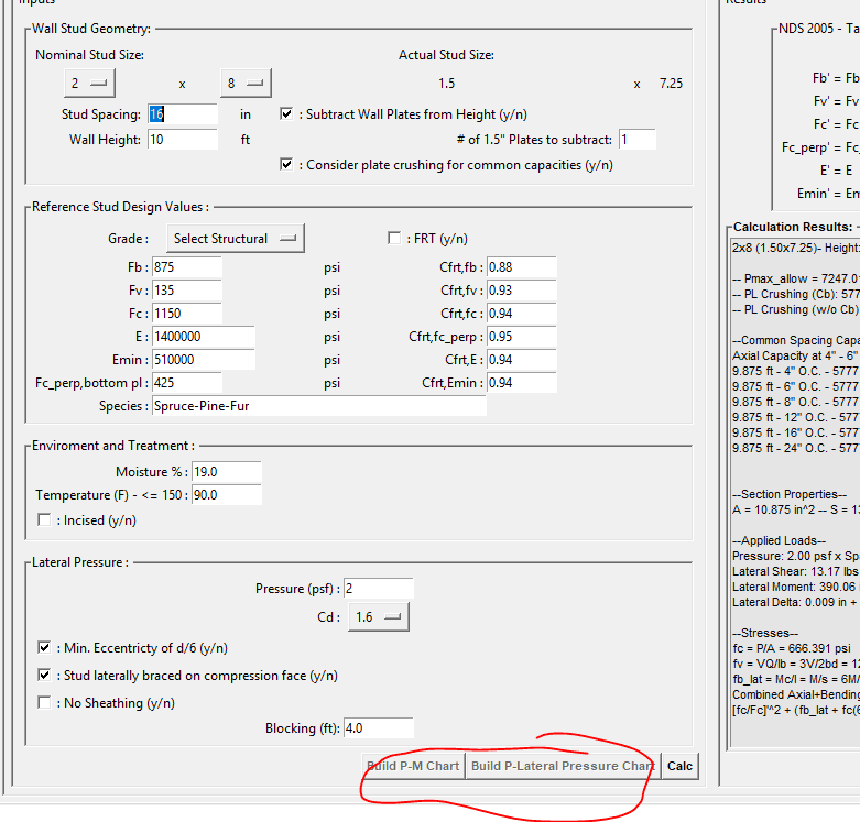
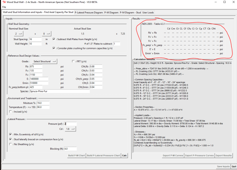
I have an issue in that it does not allow me to press the build "P-M chart" and the "P-Lateral Pressure Chart" after clicking the "calc button". see below, they are greyed out even after hitting calc:

image_2_ajuthz.png

wood_capacity_solz3a.png

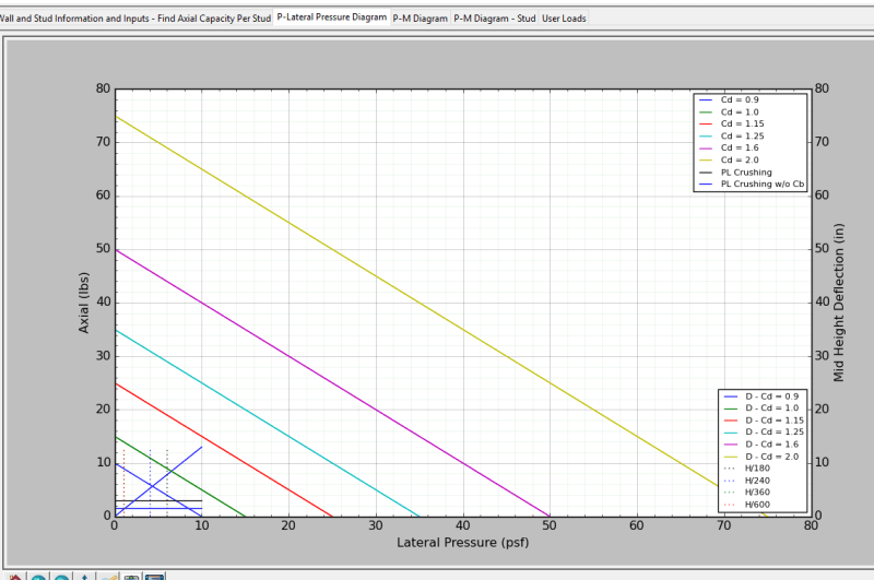
Also my p-m curve looks a little funny, I am guessing they are related.

pm_diagram_cmnktb.png


Any thoughts, am I missing something?


S&T
 
yeah the P-M curves are pre-built as just diagonal lines until they get calculated to save on some drawing time.

I'm not gettting the same thing on my end with your inputs, is anything getting written out in the command prompt window when you hit the calc button?

Edit: I just reuploaded the py files, try grabbing them, though I didn't see anything obvious as off with the ones that were out there.

Edit2: the STICKS version enables all the buttons, let me know if after you click the calc button and try to generate the curves if you get any messages in the command prompt window


Open Source Structural Applications:
 
think I got it the wood_class_file wasn't the latest one and was missing the leb definition, if you scroll your calc window the Cp portion errored out.

should be fixed now

Edit: If your ever curious as to what I've updated clicking on the history button in each folder will show the version history of the files. I try and give some detailed comments with each upload to indicate what changed and why.

Open Source Structural Applications:
 
one more quick note the GUI's are really bad about saying where they stored files when you click save or export, generally they all save to a "RESULTS" folder on your desktop.

I now know how to let you pick where to save the files instead of the hard coded location but roll out on that is slow.

Open Source Structural Applications:
 
FYI Celt, i am going to try to use this Python XY stuff to code the instantaneous center of rotation bolt calcs to try to recreate tables 7-6 - 7-13 of the AISC steel manual.

I'll let you know how it goes. I'd like to make a nice user interface and everything to review bolt layout, where the IC occurs etc.

I've got this for a school problem and the prof wants us to use excel, figured it wouldn't be to hard to code it in python and then expand on it past the school part.


S&T
 
Status
Not open for further replies.

Part and Inventory Search

Sponsor