Continue to Site

Eng-Tips is the largest engineering community on the Internet

Intelligent Work Forums for Engineering Professionals

  • Congratulations SSS148 on being selected by the Eng-Tips community for having the most helpful posts in the forums last week. Way to Go!

Wood Truss Decorative Bolted Plates

Status
Not open for further replies.

jdgengineer

Structural
Dec 1, 2011
748
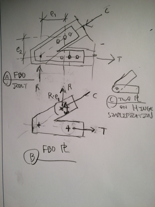
I haven't done a lot of decorative bolted trusses before. I have a simple condition, that is essentially a rafter tie truss (decorative king post in the middle but not taking load), 6x8 top chord members connected to a 6x8 bottom chord member. The joint will consist of 1/4" plates each side of the truss members with 3/4" machine bolts.

I understand how to calculate the tension/compression forces in the bottom/top chords. What I am struggling with a little bit is the design of the bolted connection and free-body diagram of the 1/4" plates.

How do you typically go about calculating this joint? The bottom chord seems like all bolts would be loaded in parallel to grain loading. But the top chord, does it not need to resolve the thrust force from the bottom chord in perpendicular to grain loading? Or am I missing something? There seems like there is an eccentricty we would have to address. Although, I suppose you could locate bolts to avoid this.

I know this is a simple problem, not sure why I am struggling, but hoping for a little bit of guidance.

 
Replies continue below

Recommended for you

Excuse the quality. Mile high sans ruler. Your instincts are solid. Locate your top chord bolt group as close to the theoretical joint as possible to reduce the moment demand on the chord, bolt group, and connection plate.

image_z5noqx.jpg


I like to debate structural engineering theory -- a lot. If I challenge you on something, know that I'm doing so because I respect your opinion enough to either change it or adopt it.
 
Thanks for the sketch Koot. Makes sense to me. I've attached my FBD as well which comes up with essentially same forces as yours.

I know you have a bit of truss experience in your background. Is this a common plate configuration or do most people try and avoid the eccentricity? I've included a second sketch which seems to avoid the eccentricity problem, but I suspect architect won't think it looks "pretty"
 
 http://files.engineering.com/getfile.aspx?folder=913ac6e8-2a67-40db-abb9-b319b9bb181b&file=FBD.pdf
You're most welcome. I've always found timber joint statics to be surprisingly difficult to parse out myself.

jdengineer said:
I know you have a bit of truss experience in your background.

True. And my wife is a specialist in heavy timber structural work.

jdengineer said:
Is this a common plate configuration or do most people try and avoid the eccentricity?

- It's an extremely common configuration. I've been seeing a lot more of it done as internal kerf plates lately.

- Another way to do it with your geometry is to allow the bottom chord to run through instead of the top. That gives you the option of sharing the moment between the chords but then leaves you with the conundrum of having to estimate how much goes where.

- While eliminating the eccentricity is appealing for us, trusses like these are obviously significant architectural elements. As such, I find that joint eccentricity is the norm, not the exception.

- Frankly, my sense is that most engineers designing these connections will either ignore the eccentricity or refuse to acknowledge that it exists in the first place.

I like to debate structural engineering theory -- a lot. If I challenge you on something, know that I'm doing so because I respect your opinion enough to either change it or adopt it.
 
Thanks for the follow-up Koot. See attached for another FBD. It seems to me that by adding a bearing plate at the bottom welded to the metal cover plates would remove all of the eccentricity on the bolts and wood members and bring all the forces internally in the plate. This to me seems like a good way to go. Thoughts?
 
 http://files.engineering.com/getfile.aspx?folder=f38bbded-b11b-4027-9057-a8101d7d2628&file=doc01253020161013095303.pdf
I agree, that version resolves the eccentricity issue nicely.

I like to debate structural engineering theory -- a lot. If I challenge you on something, know that I'm doing so because I respect your opinion enough to either change it or adopt it.
 
Jdgengineer:
I’d go one further, and put a vert. top chord end bearing pl. on the side pls. and bot. bearing pl. In effect, an end bearing shoe with side plates. Then, the bolts in the top chord will be less important/significant, except that they hold thing together and provide for roof uplift action. I would make the bot. chord pls. wider, so that I could stager the bot. chord bolts in two rows, further removed from the slope cut end of the member. I would match drill these side pls. in pairs. You could make the bot. bearing pl. 3.5" wide and long enough for A.B’s. (screws, lag screws, etc.) on both sides of the truss. Each end bearing assembly would be welded together and the truss would be drilled using them as a drilling template.
 
Status
Not open for further replies.

Part and Inventory Search

Sponsor