Eng-Tips is the largest engineering community on the Internet

Intelligent Work Forums for Engineering Professionals

Wood Truss 1

Status
Not open for further replies.

XR250

Structural
Jan 30, 2013
5,205
0
36
US
Got a job where they want a vaulted ceiling with no ridge beam. I designed 2x8 rafters with V- shaped plywood gussets. The span is only about 8.5 ft. The builder got a quote from a truss company and they are proposing what is attached.
Basically, using the nail plate to act as a moment connection at the peak. Seems a bit sketchy to me.
What do you think?
 
 http://files.engineering.com/getfile.aspx?folder=1a09687c-1193-4ae5-b7b5-fda5ab9d62e6&file=TRUSS.pdf
Replies continue below

Recommended for you

So I'm not Koot, but I have worked at a place that manufactured trusses. Seems to me that with such a short span, if the plates are installed properly into that super-dense wood (read, lots of passes with the press) then I'd think it would be ok. Besides, it would be MiTek's stamp on the line, and those folks tend to know what they're doing with their truss plates.

Please remember: we're not all guys!
 
I'll jump in too:

I noticed a 10 psf Bottom chord dead load mentioned that is not actually there since this is just a 2X8 instead of an actual residential open web truss...

I also noticed a horizontal force of 18# due to uplift, but no horizontal kick due to any snow or dead load - that seems really questionable.

I assume the 30 psf snow is for the site and is not their minimum design snow load for all trusses?

I, too, am a little leary regarding the ridge connector. Personally, I would like to see calculations verifying the connection.


Mike McCann, PE, SE (WA)


The EOR is always responsible for delegated work not just MiTek. I have had a number of issues with Mitek in the past on truss designs they provided. Loading on the MT20 plates only shows tension and compression.

Not that it matters much but I have never seen a vaulted roof using a plate, a beam or scissor truss.
 
Looks like an arch. Better make sure you either account for lateral kickout forces at the top of your bearing wall or detail to not allow these forces to develop. And make sure that you are on the same page with the truss mfr on lateral deflections/forces at bearing wall.
 
SEJohn said:
Looks like an arch. Better make sure you either account for lateral kickout forces at the top of your bearing wall or detail to not allow these forces to develop. And make sure that you are on the same page with the truss mfr on lateral deflections/forces at bearing wall.

They are not showing any lateral thrust. That was my first inclination as well.
 
Another thought..

These press plates are designed, as far as I know, to take either all tension or all compression loads across the entire plate, with the forces normal to the press plate embedded shear tabs.

I have never seen these tabs used to transfer tension/compression top, and compression/tension bottom within the same press plate.

Mike McCann, PE, SE (WA)


There is a note which states that "Rigid ceiling directly applied". I think you need advise that the ceiling is vaulted. I agree with the others, I would count on a truss plate forming a moment connection in timber.

Why no ridge beam? It will be hidden by the ceiling. If not you will need to design the wall for the thrust.
 
OK.

Use a W12 ridge beam and upset it. Can detail that to get a good ridge vent situation too using the 2X8 rafters.

After all, all they are worried about is the look on the interior, right?

Mike McCann, PE, SE (WA)


It is for an exterior corridor so venting is not a problem. They want 2x8 rafters so an i-beam to fit is not possible with the clean interior peak
 
Oh sure, I take one day off to write the PE and I miss out on my own personal summons. I'll mostly be reiterating other statements but here we go:

- I've never once seen this proposed in a real structural application. Back in my day, there wasn't a TPI method, nor a software option, for designing plated moment connections. Perhaps that has changed.

- All of the software packages that I used in the nineties had magic key combinations that you could use to hide the error messages in a bogus design. This may be that.

- In the plant, we used to make all kinds of pseudo structural stuff that involved non-designed, plated moment connections. It seemed to work quite well. One example in particular was a shelf system for plate storage that had 2x cantilevered out from such a joint.

- Used like this, the creep associated with each plate tooth will contribute to deflection in a manner much more severe than you'd get with a normal, axial only, truss connection. I'd like to know that was considered in the design. That said, my gut feel us that this would actually out perform your gusset plate solution with respect to stiffness. We never really saw any sag in those shelves that I mentioned.

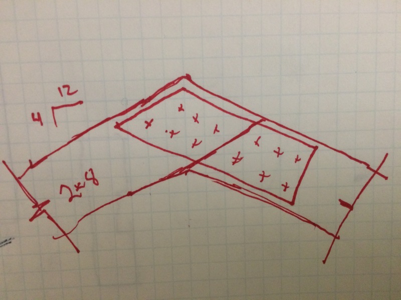
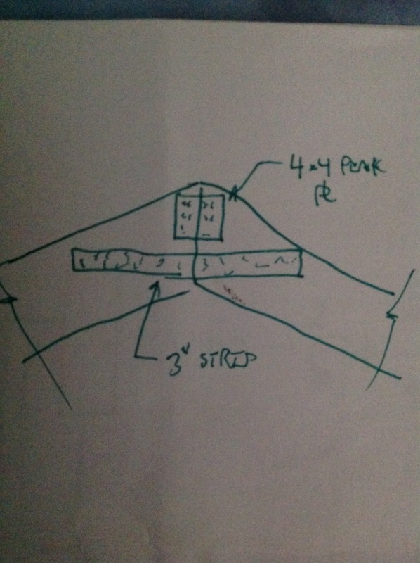
- Rationally, one could simply count on only the lower third of the plate as a stand alone, tension only connector and prosecute the design on that basis using accepted TPI design principles. I doubt tthat the fabricator did that but Mitek could. The plate probably buckles at the top by the numbers anyhow. And, the rafters being as shallow as they are, the tension connection would be mostly parallel to grain anyhow which is helpful.

- Obviously, none of us wants to discourage innovation and economy. Because this is an unconventional application, I would ask for detailed calculation output on the joint and truss and ask that the design be revised and stamped by a Mitek rep. Mitek for two reasons. Firstly, like SLTA mentioned, they know their stuff. Secondly, they're a lot more liability cocious than the fabricators. 50/50 odds they veto it I bet.

I like to debate structural engineering theory -- a lot. If I challenge you on something, know that I'm doing so because I respect your opinion enough to either change it or adopt it.
 
I thought about the couple analogy with the lower portion of the plate acting in tension and the upper portion of the wood bearing taking the compression. My concern was also plate teeth creep in addition to wood shrinkage. This geometry is not friendly to either. I have to disagree that this is stiffer than a 3/4" plywood gusset on each face - my intuition tells me otherwise. I am going to take your suggestion and get one of the mitek folks to sign off on it. Even so, I will have disclaimers on my drawings and show my detail as a better alternative :>

Thanks for everyone's help.
 
One could perhaps devise a more convincing version without compromising the intent. At the scale we're talking about, I'd happily stamp the detail below with 18 ga plate stock.

IMG_0349_jdd0od.jpg


I like to debate structural engineering theory -- a lot. If I challenge you on something, know that I'm doing so because I respect your opinion enough to either change it or adopt it.
 
Original detail seems to have a lot of extra material not located where the maximum forces are...just an opinion from the woods...
 
There is one aspect of the gusset detail that I'm curious about. The reenteant corner at the tension side of the peak will cause a notch like stress concentration that would be the death of 2x material etc. Are tension side stress concentrations not an issue with plywood? I could see how the laminate/particulate nature of plywood might improve that aspect of behaviour but I've never seen anything in print to that effect. Not that I've looked especially hard.

I like to debate structural engineering theory -- a lot. If I challenge you on something, know that I'm doing so because I respect your opinion enough to either change it or adopt it.


IFRs said:
Original detail seems to have a lot of extra material not located where the maximum forces are...just an opinion from the woods...

Your a frickin Petroleum Engineer, why should I listen to you [bigsmile] Thanks for the input. I honestly did not spend much time optimizing the detail as the fee was really low on this one.

KootK said:
There is one aspect of the gusset detail that I'm curious about. The reenteant corner at the tension side of the peak will cause a notch like stress concentration that would be the death of 2x material etc.

My gut feel was that the laminated nature would negate the notch issue in a low stress application like this one anyway.

Here is an easier idea that i should be able to make work...
 
 http://files.engineering.com/getfile.aspx?folder=9e2381a0-bb02-4453-8536-27fb0ecac326&file=2x8.png
If you've already got it designed and detailed, I'd stick with what you've got. It's a good detail and I assume that you went 4' to use strips out of a common sheet. The sketch below shows an alternate option for both kinds of plate.

IMG_4835_c05atr.jpg


I like to debate structural engineering theory -- a lot. If I challenge you on something, know that I'm doing so because I respect your opinion enough to either change it or adopt it.
 
Status
Not open for further replies.
Back
Top