Eng-Tips is the largest engineering community on the Internet

Intelligent Work Forums for Engineering Professionals

  • Congratulations waross on being selected by the Tek-Tips community for having the most helpful posts in the forums last week. Way to Go!

WUF-W Connection 4

Status
Not open for further replies.

Rantamental

Structural
Feb 17, 2016
12
0
0
IR
Hi Guys,
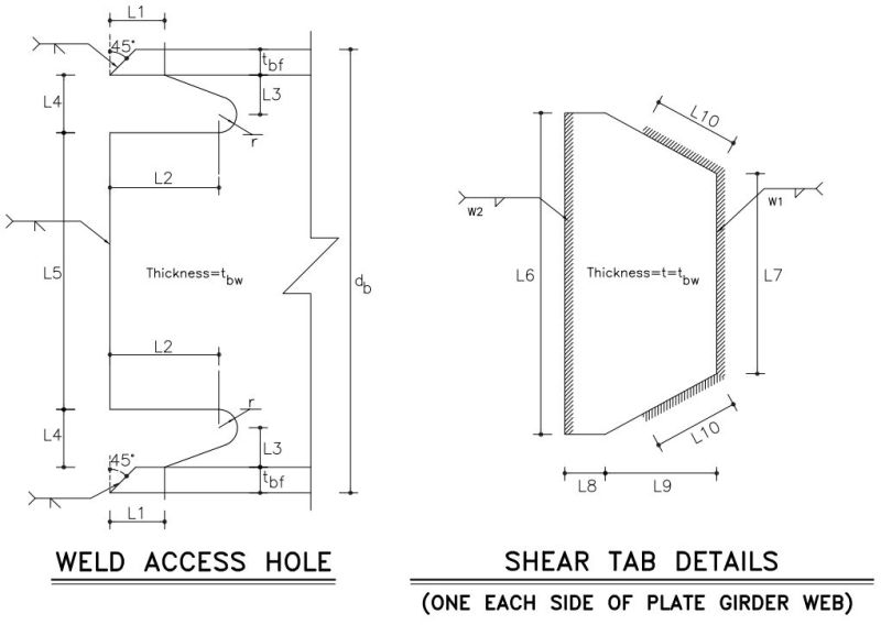
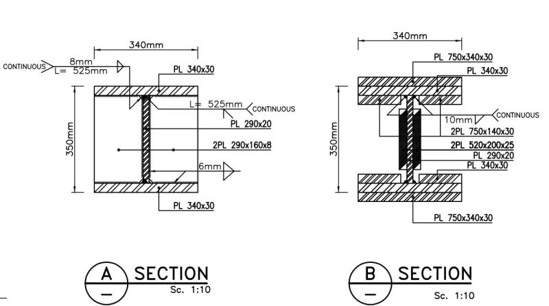
Recently our company structural engineers team have designed a high rise steel structure with special moment frames system+ special bracing frames which boosted by rotational friction dampers and used WUF-W connection for connecting beam to column. According to ACI-358-16 (PreQualified steel connections) ,section 2.3.2a Built-up Beams Members, The web and flanges shall be connected using CJP groove welds with a pair of reinforcing fillet welds (min 8mm) within a zone extending from beam end to a distance not less than one beam depth beyond the plastic hinge.
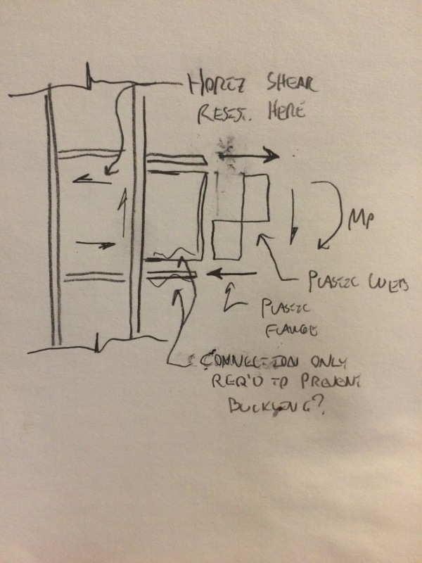
Also according to WUF-W criteria, beams should conform the requirements of Section 2.3., And according to Section 8, the plastic hinge location shall be taken to be at face of the column, So protected Zone is a distance equal depth of the beam at face of the column and in this zone, Welding flange and web of the beam should be CJP+ 8mm (Min) fillet weld in both side of the web.
Our Design was similar to above descriptions completely, Also WPS and Welding Maps of shop drawings prepared true But unfortunately steel manufacturer contractor did not observe these limitations and has connected web and flange just by a 8mm to 12mm fillet weld according to web thickness in both side, therefore there is not any sign of CJP welding.
Now one-fifth of structure has been constructed and erected and we are looking for any criteria for acceptance of as built connections or any other implement works like repairing or retrofitting the connections to satisfy prequalified connections code.
Your prompt answer will be appreciated.
 
Replies continue below

Recommended for you

Did the contractor not submit steel shop drawings for your review? Did they show cjp welds and decide to do something else without telling anyone?

If you have space, one option may be to bolt on flange plates or the Kaiser bolted bracket.
 
Thx for your reply
Yes, All shop drawings have been submitted and signed by all stakeholders, also they have accepted their's fault but it is not solution, the main question is, what is the best solution?!
If we add bolts on flanges or any thing like that, we can not change the criteria that we need CJP groove weld in protected zone, in all connections we need cjp because of plastic hinge and high degree of rotation in this zone and high level of fracture in this location
So what we have to do?!
 
I'm not sure how practical this is but can they remove the welds and cjp? Is there a bevel on the wide flange beam as would have been shown on the steel shop drawings? (i.e. was beam ready for CJP weld?) Why was there not a special inspector for these welds? There appears to be a combination of errors going on here...

With that said, can you revise to a different prequalified connection? I had suggested the Kaiser bolted bracket. I believe that does not require welding. We've used it in the past to retrofit pre Northridge moment frames. Any potential for this?
 
The issue is not the connection but the built-up beam. Adding to the beam connection at the end will not address the built-up members deficiencies. The requirements for connections and members in AISC 358 are all tested, you can try and have your connection tested per chapter K. You are going to have to involve the authority having jurisdiction and setup a review panel. Have the connections tested and hope that the fillet welds pass, since you are testing you can also test a configuration with bigger fillet welds, etc
 
Dear jdgengineer You are true, there are a lot of issues that are hidden in this problem and another teams are checking legal documents, it has an expert welding inspector but ... :)
About CJP, comment of sandman21 is true completely,Connection Type will specify length of protected zone at face of column and in this zone we have to connect flange and web by CJP groove weld. Also in AISC 358 in built up section has been stated built up members should be similar to rolled section and i think it want to achieve a uniform section to see a uniform plastic deflections with minimum deficiencies and fractures. Therefore it seems the CJP is mandatory!
About Kaiser Connection in AISC 358 section 9.3.1 has mentioned Beams shall be rolled wide-flange or built-up I-shaped members conforming to the requirements of Section 2.3., then this type of connection needs CJP welds too.
Finally the only way is testing,is not?
 
So there is not any way except testing according to AISC-358 provisions ?
any thing like repairing or retrofitting ?
assume this building had built some years ago and web and flange of built up beams connected by fillet welds, there is not any way to retrofit them according to FEMA ?
 
I think that sandman's post was pretty spot on. If you wish to pursue an alternate compliance route, it's time to start talking to your AHJ.

In my opinion, the main lesson that the structural engineering community learned from Northridge is that structural engineers aren't great at predicting cyclic connection ductility. That's why decided to stick to systems that have been previously verified by testing (prequalified). Out of pragmatism, we do set the bar a bit lower for retrofits. It's a slippery slope to start classifying the correction of new build mistakes as retrofits however.

Is there any way to modify your system so that less ductility is required and some of the mure onerous requirements would no longer apply?

I like to debate structural engineering theory -- a lot. If I challenge you on something, know that I'm doing so because I respect your opinion enough to either change it or adopt it.
 
FEMA 351 addresses retrofitting as a reference from ASCE 41 but it doesn't look like it will help you too much here if you were allowed to use FEMA 351. I would have them gouge out the welds and install the connection like it was intended or look at another system if you qualify (like Sideplate), but I think that would still require removing what is in place so it doesn't interfere with the new system function.
 
Rantamental:
You don’t show any element sizes or thicknesses, nor do you spell out the beam depth (protected zone length). You do say 8 or 12mm fillets, each side, as a function of the web thickness; pretty typical built-up beam fab., actually/normally a function of the shear flow. It would be helpful if you showed a couple sketches of these beam connections with all dimensions and weld sizes, etc. The reason for the CJP weld, flange to web, in that region is the extreme energy absorption actively going on in that region during hinge formation and reversal, and the want/desire to be more sure that there is no unprotected weld roots, with lack of fusion, crack starters, etc., during that high stress activity. Could you back gouge, from one side only, through the fillet and web and into sound metal at the root of the other fillet, providing a new groove to be rewelded for length “d” (beam depth, plus) out into the beam. Half of these welds would be down hand and half over head, but from only one side. I would probably preheat (post heat?) the connection to slightly soften or relax the region re: residual welding stresses, etc. And, I would not over match (by much) the base metals with my weld filler metals and process, so as to allow as much ductility as possible. I’d sure want the advice of a good welding engineer/metallurgist in setting up my weld procedure, process, etc. Then, I’d probably take him with me to meet with the AHJ for their approval.
 
Sideplate still has the same CJP/fillet requirement A retrofit generally does not bring your building up to current code level, assumptions regarding the life of the building are incorporated this lower some requirements you would typically need to provide. FEMA 351 would require project specific testing to qualify your retrofit connection, so you are back to the same place you are at now.
 
Agree on 351, that's why I said "if you were allowed to use" which is highly unlikely. I wouldn't allow 41/351 etc.. rehabilitation methods on a newly built building if I was the building official or the owner.
 
Hi
Thanks a lot for your help on this issue, thanks to all
At first i want to explain just a little more about our project.
Our Structural system is special moment frames in two directions and general arrangement of frames is Tube in Tube system with a rigid core in middle.
In external tube , Columns are closely together and we have a column in each 3 meters, so the depth of beams will be limited about one-seventh of clear span of that, Assume that Longitudinal dimension of column is 600mm, So clear span of beam will be 300-60=240mm and total depth of girder will be limited to 240/7 ( Approximately 350 mm).
We have wide range of spans and wide range of girder depth too. they have been summarized in following tables :
Screenshot_-_3_14_2017_3_19_04_PM_v7zqbk.jpg

Screenshot_-_3_14_2017_3_17_34_PM_ti0pzv.jpg

Screenshot_-_3_14_2017_3_18_12_PM_dcbde2.jpg

Screenshot_-_3_14_2017_3_18_28_PM_w34jni.jpg

Also Following detail is general type for our connections and beam splices.
Screenshot_-_3_14_2017_3_29_38_PM_wxul3q.jpg

Screenshot_-_3_14_2017_3_29_56_PM_ivddgj.jpg
 
We Asked this issue from AISC 358 committee and they offered 3 options
1- The contractor could remove and replace the non-complying members. I recognize that this would be very costly and possibly dangerous. However, this solution would bring you into compliance
2- The contractor could burn off the existing welds, properly prepare the webs for CJP welds, and then complete the CJP weld. I recognize that this would be very costly and possibly dangerous. However, this solution would bring you into compliance
3- Connections in IMF and SMF must be either prequalified or qualified by testing. Requirements are provided in Chapter K of the AISC Seismic Provisions. Though not exactly what was intended, you might choose to “post-qualify” the connections that exist in the structure. This would involve building test subassemblages reflecting the actual conditions and then testing them per Chapter K of the Seismic Provisions. If the tests are successful then the conditions can be left as they are. If not then they will have to be repaired. This option might be a good one for gamblers. The tests will not be cheap (over a decade ago I got an estimate of three tests required per configuration at about $50,000 per test). If the tests work the testing may be cheaper than the repairs. However if they do not work you will have the cost of the tests and the repairs

So it seems there is not any simple way !
 
Thanks for the updates. It's an interesting problem to be sure.

I've been thinking about how one might reinforce this if one were in fact alllowed to reinforce it. You know, first principles. And that got me to wondering: why are these demand critical welds?

At first, I thought that the answer would be obvious. You have to develop the plastic moment so you have to develop reliable horizontal shear transfer to go along with that. But that's not actually true. On the column side of the hinge, 100% of the required horizontal shear capacity is provided by the column panel zone. So there's no problem there.

With respect to important jobs that the welds are doing, all I can come up with is that they prevent the compression flange and web plate edge from buckling. And one would think that would be a relatively easy thing to reinforce for. But, then again, there is that clever engineer hubris problem that I mentioned earlier...

IMG_5401_gsemws.jpg


I like to debate structural engineering theory -- a lot. If I challenge you on something, know that I'm doing so because I respect your opinion enough to either change it or adopt it.
 
Because the area at the hinge zone will see inelastic behavior, buckling of the web, force redistribution to the flanges as the web loses capacity, etc. Your analysis stops at what a beam would do under static elastic loading. Its possible that a thicker fillet weld or even current fillet would work but the demand on the connections and plastic hinges are such that testing is needed to understand the behavior.
 
sandman said:
Your analysis stops at what a beam would do under static elastic loading.

Not so. My sketch and analysis specifically detailed forces associated with plasticity and the web and flange buckling that might occur under cyclic dynamic loading. One can only get so "dynamic" in a quick, 2D, stationary sketch. I get that testing is required for complete understanding and alluded to it twice above myself. I'm trying to dive a little deeper.

I like to debate structural engineering theory -- a lot. If I challenge you on something, know that I'm doing so because I respect your opinion enough to either change it or adopt it.
 
Your sketch is true at face of the column, also we check shear by plastic moment and value of this shear is clear, so we design dublar plate in column's web to control shear. When a girder play a moment frame role in cyclic loading it will see some rotations and deflections that did not consider in elastic design. Please watch cyclic test of wuf-w or RBS connections in youtube, the mechanism of wuf-w fracture is clear and plastic hinge occurs exactly in beam at face of column. The main issue is that we need a uniform section in this location to sure that it satisfies the criteria of codes for rotations (0.04 radian)
So the welding in this location is not according to capacities.
Therefore if beam fails before complete rotations beacuse of weakness in protected zone, ductility of system will reduce and whole of frames will collapse.
 
Rantamental said:
When a girder play a moment frame role in cyclic loading it will see some rotations and deflections that did not consider in elastic design.

No worries, I'm with you on this. Everything in my previous responses assumed and implied cyclic, inelastic behavior.

Rantamental said:
The main issue is that we need a uniform section in this location to sure that it satisfies the criteria of codes for rotations (0.04 radian)

Firstly, with the right reinforcement scheme, I suspect that you could create a section capable of achieving full plastic section moment over 0.04 radians. That's pretty much what I've been getting at.

Secondly, while I agree that it's necessary to achieve the 0.04 radians, I'm not sure that it's really necessary to achieve the full section plastic moment. All that matters is hitting that level of rotational ductility while maintaining a substantial measure of load resistance. Were the web flexural capacity to be considered sacrificial, you might get some degree of strain softening which is always undesirable. I would argue that the impact would be small and that normal strain hardening would kick in after an initial dip however.

Rantamental said:
So the welding in this location is not according to capacities.

It's important to remember that, in these systems, we're primarily designing for a particular amount of rotational/displacement capacity, not a particular level of load resistance. Consequently, there really is no required load capacity for the welds in this situation other than that expected to arise as a result of rotation. The litmus test for successful performance is simply whether or not the welds remain in tact up to the 0.04 radian displacement so that the web and flanges continue to stabilize one another locally. At least that's my take on it.

Rantamental said:
Therefore if beam fails before complete rotations beacuse of weakness in protected zone, ductility of system will reduce and whole of frames will collapse.

If you stabilized the flanges to prevent local buckling, I would argue that you likely would still achieve complete rotation capacity. You might even be able to achieve that rotation at a lower Mp as a result of the web not participating fully which would serve to increase the safety margins on the member of your system designed for capacity/over strength.

With this situation, I feel that the following is likely true:

1) You won't be able to negotiate any further with the AISC 358 committee. You'll simply have to do as they've instructed already. As such, I wouldn't waste too much time trying to argue your way into a lower cost solution.

2) My, very strong, gut feel is that you've got a great system here and that the code deficient welding really does not compromise that. Another thing that you've got going for you here is that the entire perimeter of your building is moment frame rather than just having a few isolated moment frames. And you've got the rigid core. That means a lot of redundancy so, if a handful of welds did give way AND that materially affected the performance in a few of those failures, would that really be such a big deal? I would argue not.

3) The cost of the remedy, per the AISC 358 committee, will be enormous. As the engineer of record, I would consider it my duty to the client, and society at large, to at least make a modest attempt at selling the AHJ on a non-tested reinforcement fix. That, even acknowledging that your odds of success would be extremely low.

4) The only way that you'll have a fighting change of being successful with #3 is if you're able to tell a good story about why the system is fine as is. A story that speaks to the fundamentals of the behavior that the code provisions are intended to encourage. I'm trying to help you come up with that good story.


I like to debate structural engineering theory -- a lot. If I challenge you on something, know that I'm doing so because I respect your opinion enough to either change it or adopt it.
 
Status
Not open for further replies.
Back
Top