Eng-Tips is the largest engineering community on the Internet

Intelligent Work Forums for Engineering Professionals

WUF-W Connection 4

Status
Not open for further replies.

Rantamental

Structural
Feb 17, 2016
12
0
0
IR
Hi Guys,
Recently our company structural engineers team have designed a high rise steel structure with special moment frames system+ special bracing frames which boosted by rotational friction dampers and used WUF-W connection for connecting beam to column. According to ACI-358-16 (PreQualified steel connections) ,section 2.3.2a Built-up Beams Members, The web and flanges shall be connected using CJP groove welds with a pair of reinforcing fillet welds (min 8mm) within a zone extending from beam end to a distance not less than one beam depth beyond the plastic hinge.
Also according to WUF-W criteria, beams should conform the requirements of Section 2.3., And according to Section 8, the plastic hinge location shall be taken to be at face of the column, So protected Zone is a distance equal depth of the beam at face of the column and in this zone, Welding flange and web of the beam should be CJP+ 8mm (Min) fillet weld in both side of the web.
Our Design was similar to above descriptions completely, Also WPS and Welding Maps of shop drawings prepared true But unfortunately steel manufacturer contractor did not observe these limitations and has connected web and flange just by a 8mm to 12mm fillet weld according to web thickness in both side, therefore there is not any sign of CJP welding.
Now one-fifth of structure has been constructed and erected and we are looking for any criteria for acceptance of as built connections or any other implement works like repairing or retrofitting the connections to satisfy prequalified connections code.
Your prompt answer will be appreciated.
 
Replies continue below

Recommended for you

Isn't it true that those welds became demand critical after the Northridge Earthquake revealed numerous brittle failures at this location in steel moment frame?
 
I know about Northrige failures in the ubiquitous CJP beam column connections. I wasn't aware of anecdotal examples of web plate to flange plate weld failures in built up moment frame beams. Certainly, I'd be interested to hear about such examples if they're kicking around out there.

I like to debate structural engineering theory -- a lot. If I challenge you on something, know that I'm doing so because I respect your opinion enough to either change it or adopt it.
 
What you are describing is a welded flange bolted web moment connection, which is a pre-Northridge moment connection and was part of the reason for the failures. Northridge not only had weld failures but failures of panel zones and flange rupture, during a moderate earthquake. The engineer has an obligation to the client to provide the building they paid for, contractor errors of this magnitude should not be passed off by telling a good story. This is partially how we were caught "unaware" of the issues with moment frames before Norhtridge. We only have a small picture of what the building looks, removal of perimeter moment frames could have large impacts on the core structure which were not anticipated. You are going to have to come in compliance with AISC 358 or provide testing.
 
sandman said:
What you are describing is a welded flange bolted web moment connection, which is a pre-Northridge moment connection and was part of the reason for the failures.

Not at all, assuming that you're addressing my proposals here. I'm talking about a system where the vertical shear resistance remains as it started: as passing through a web welded to the column flange. That ameliorates the differential vertical stiffness issues associated with bolted web connections.

sandman said:
The engineer has an obligation to the client to provide the building they paid for

I don't know the contractural arrangements of the project. There are arrangements under which the owner may well share in the cost and schedule savings associated with avoiding a needless repair. Regardless, at the end of the day, all resources are society's resources and they should be deployed efficiently.

sandmam said:
contractor errors of this magnitude should not be passed off by telling a good story.

Even if it's the correct story? You seem to imply that I'm being cavalier about the whole thing. I'm not. I'm attempting to be creative, flexible, and technically responsible. Everybody makes mistakes. And that includes engineers as well as contractors and fabricators. As much as possible, my preferebnce is to work with folks creatively and collaboratively to correct miststakes rather than to just beat them over the head with inflexible regulations. High seismic design, of course, has gone the other way out a combination of real and perceived necessity.

I like to debate structural engineering theory -- a lot. If I challenge you on something, know that I'm doing so because I respect your opinion enough to either change it or adopt it.
 
KootK said:
You might even be able to achieve that rotation at a lower Mp as a result of the web not participating fully which would serve to increase the safety margins on the member of your system designed for capacity/over strength.
The system you are describing is the thought process for moment prior to to Northridge.

KootK said:
Even if it's the correct story? You seem to imply that I'm being cavalier about the whole thing. I'm not. I'm attempting to be creative, flexible, and technically responsible. Everybody makes mistakes. And that includes engineers as well as contractors and fabricators. As much as possible, my preferebnce is to work with folks creatively and collaboratively to correct miststakes rather than to just beat them over the head with inflexible regulations. High seismic design, of course, has gone the other way out a combination of real and perceived necessity.

What part of your story is correct? You cant answer the fundamental questions regarding behavior or forces in the beam web during a seismic event or even testing. You would have to begin at that point to try and convince anyone that your creative approach satisfies the intent of the requirements. Your assumption regarding failures in perimeter moment frames not being a big deal, without knowing the configuration or performance criteria of building is also unconvincing to try and tell the story that the welds are satisfactory. Its not a matter of being cavalier its matter that your story lacks fundamentals.
 
KootK said:
With respect to important jobs that the welds are doing, all I can come up with is that they prevent the compression flange and web plate edge from buckling. And one would think that would be a relatively easy thing to reinforce for. But, then again, there is that clever engineer hubris problem that I mentioned earlier...

Not sure how easy it would be to quantify the force required at this joint since the weld strains will need to be compatible with the distortions caused by local flange buckling that will occur after multiple cycles. Testing has shown that nominally sized fillet welds at this joint have proven to be the weak link (Link). The AISC 358 commentary mentions that most of the testing done on built-up beams used end-plate moment connections, and if we look at section 6.4 we see that the requirement for CJP welds is relaxed to fillet welds sized at 75% of the web thickness. I suspect that as long as the welds are sized to develop the tensile strength of the web (75% thickness), there is a strong chance that the system will behave as intended.

Rantamental...Testing will be required, no doubt about that. But I think you would put the odds of success in your favor if you tested a configuration that used fillet welds sized at 75% of the web thickness. The contractor would need to repair the welds that don't currently meet that, but that would be a lot less work than repairing with CJP welds. I would also make the welds demand critical given that yielding is expected in this region, although this is not required by AISC 341 as far as I can tell.
 
sandman21 said:
.The system you are describing is the thought process for moment prior to to Northridge.

I'd agree if my proposed shear resistance mechanism were soft or brittle. It's neither.

sadman21 said:
What part of your story is correct?

Possibly all of it. Definitely the significant observation that there is a limited demand for the web to flange welds to serve as horizontal shear transfer.

sandman21 said:
You cant answer the fundamental questions regarding behavior or forces in the beam web during a seismic event or even testing.

As I see it, I've been been meticulously answering all of these questions. What exactly is it that you believe that I've missed?

sandman21 said:
Your assumption regarding failures in perimeter moment frames not being a big deal, without knowing the configuration or performance criteria of building is also unconvincing to try and tell the story that the welds are satisfactory.

OP said that this was a perimeter tube moment frame system with tight column spacings (Fazlur Khan variety). I took him at his word, particularly after he posted details that would seem to confirm the assumption. The permiteter tube moment frame system embodies a lot of redundancy as I mentioned. It's an internet forum for Pete's sake. If we all hung back waiting for complete information, nothing would ever get done.

sandman21 said:
Its not a matter of being cavalier its matter that your story lacks fundamentals.

I disagree. If anything, I believe that I've been doing more than my share to chase down the fundamentals. Heck, I'm the only participant other than the OP to post a sketch. Most of what's materialized here seems to be just "follow the code" and the usual seismic catch phrases about ductility etc. I understood that OP wanted some out of the box problem solving and that's what I've been attempting.

I like to debate structural engineering theory -- a lot. If I challenge you on something, know that I'm doing so because I respect your opinion enough to either change it or adopt it.
 
Deker said:
Not sure how easy it would be to quantify the force required at this joint since the weld strains will need to be compatible with the distortions caused by local flange buckling that will occur after multiple cycles.

Probably not too easy. My intention was to try to hone in on just what we need the welds for and then, using that information, try to generate an intelligent reinforcement scheme. Similar to your recommendation regarding the 75% welds, one might just default to trying to replicate the original capacity/rstraint condition.

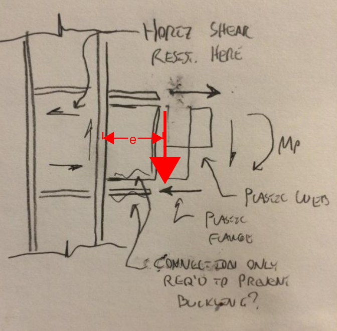
With reinforcement in play to address other issues, my biggest concern with my previous proposal would be the need for the potentially disconnected web to resist the moment implied by the eccentricity of shear delivery at the hinge (red stuff below). There's no doubt that the omission of the penetration weld make things less good. The more interesting question, in my opinion, is whether or not that makes things less than good enough. It's tough to say without testing of course.

Capture_if2p5h.png


I like to debate structural engineering theory -- a lot. If I challenge you on something, know that I'm doing so because I respect your opinion enough to either change it or adopt it.
 
KootK said:
There's no doubt that the omission of the penetration weld make things less good. The more interesting question, in my opinion, is whether or not that makes things less than good enough. It's tough to say without testing of course.

Based on the research in the link I posted above, we know that nominally sized fillet welds are not good enough. For the built-up sections that were tested, the failures initiated with yielding, followed by flange local buckling, followed by flange-to-web weld rupture. It's clear that the distortional forces caused by flange buckling place excessive demands on the welds. Since these forces are next to impossible to quantify, the prudent course of action is to size the welds to develop the web. Although I appreciate your effort to think outside of the box, the analysis in your sketch could never have predicted that type of failure. In this case the decision to develop the web is not the default choice for the sake of conservatism, it's a carefully considered choice given all of the information available.

In my mind this is similar to the new requirement in AISC 341-16 to size gusset plate welds to develop the strength of the plate for SCBF systems detailed to buckle out-of-plane. Testing showed that weld tearing was caused by out-of-plane rotation demands on the gussets due to brace buckling. That never would have been captured by traditional analysis.

 
Deker said:
Based on the research in the link I posted above, we know that nominally sized fillet welds are not good enough.

1) Any chance you'd want to reference some specific pages or sections to save me a bit of review time? I wan't to benefit from what you've shared but the document is 250 pages.

2) I mispoke. Please consider my previous comment revised as follows:

KootK ORIGINAL said:
The more interesting question, in my opinion, is whether or not that makes things less than good enough.

KootK REVISED said:
The more interesting question, in my opinion, is whether or not that makes things less than good enough when strategic reinforcing has been implemented.

Strategic reinforcing being something less onerous that gouging and full CJP of course.

Deker said:
the analysis in your sketch could never have predicted that type of failure.

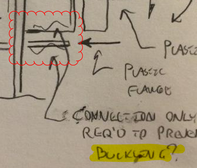
But I did predict that type of failure in my sketch as being the critical issue. That's what the squiggly line and the reference to buckling were about. And based on the research that you provided, it kinda sounds as though I might have been on the mark. So perhaps engineering judgement is still worth a little something after all.

Deker said:
Since these forces are next to impossible to quantify

I don't see why it should be impossible. We do very much the same thing when providing restraint to rebar in the plastic hinge zones of shear walls etc. And again, a fall back position could be to reinstate the tensile capacity of the web by some means other than CJP welding.

I think that it's worth noting that we're all in agreement about most everything here. Very early on in this thread, I myself stated that 358 compliance would almost certainly be required. And I elaborated on why I thought that justified. I also brought up many of the same issues related to cyclic, inelastic behavior that are now being used to critique my own ideas. All I'm doing here is extending the conversation in an attempt to further understanding and creative problem solving.

Capture_tgjikp.png


I like to debate structural engineering theory -- a lot. If I challenge you on something, know that I'm doing so because I respect your opinion enough to either change it or adopt it.
 
I'm going to continue to address any concerns raised about my work here. That said, I'm also going to try to scale back my involvement in this thread. I have empirical evidence that, when I start doing a lot of quoting, the villagers start to reach for their pitch forks.

I like to debate structural engineering theory -- a lot. If I challenge you on something, know that I'm doing so because I respect your opinion enough to either change it or adopt it.
 
Check out sections 6.5, 6.6, 7.2.4. When I read your statement I took it to mean that you could size the weld to prevent flange buckling. Based on the testing, flange buckling is inevitable and this creates a demand on the weld. That is the force that I believe is difficult to quantify. More of a deformation compatibility force, except the exact deformations are not known with any certainty.

KootK said:
3) The cost of the remedy, per the AISC 358 committee, will be enormous. As the engineer of record, I would consider it my duty to the client, and society at large, to at least make a modest attempt at selling the AHJ on a non-tested reinforcement fix. That, even acknowledging that your odds of success would be extremely low.

This is only statement you've made that I take exception with. The testing has shown nominally sized welds to be deficient. I don't believe it is possible to prove otherwise without additional testing.
 
Thanks for the references. Certainly, I agree that an untested reinforcement fix should never be considered as rigorously proven as a successfully tested fix. I take that to be self-evident.

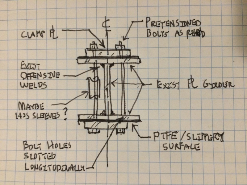
For interest's sake, imagine a hypothetical alternate universe in which Northridge had not happened and we were still at liberty to merrily apply our own, hubris laden engineering judgements. How would you go about specifying a reinforcement fix? I've shown a proposal of my own below for review. Some things that I was hoping to accomplish:

1) Prevent flanges from pulling away from webs.

2) Prevent reinforcement itself from increasing the plastic hinge yield moment.

3) Avoid unacceptable stress risers.

The one weakness that concerns me is that I worry that the pretension in the bolts might mess with the welds if the flanges to not bear tightly against the web.

2017-03-15_21.32.06_xqfwqs.jpg


I like to debate structural engineering theory -- a lot. If I challenge you on something, know that I'm doing so because I respect your opinion enough to either change it or adopt it.
 
In the alternate universe I would still replace the welds with larger fillets since I believe that would be less work than what you propose...just a gut feel though. That said, I don't mind what you propose (in the alternate universe, of course).
 
Yes, the beefed up welds would be much less work. They'd also not encroach spatially which may well be critical. I'm confused though: do you think that the beefed up welds would work in Bizzaro world? I've been getting mixed massages on that.

I like to debate structural engineering theory -- a lot. If I challenge you on something, know that I'm doing so because I respect your opinion enough to either change it or adopt it.
 
As I wrote in my first post, I suspect fillet welds that develop the strength of the web would work in the real world, but I wouldn't bet my license on it.
 
I don't have any experience designing special moment frames, but the challenge Rantamental is facing and the discussion in this thread has been quite interesting to follow. For my own education on this topic, I have been studying the AISC and NEHRP guidelines on WUF-W connections and wanted to raise some issues for discussion and to further my understanding.

1) The particular girder detail shown has 30mm thick flanges, which are slightly thicker than the 1" limitation in AISC-358. Also, the clear span-to-depth ratio (2400mm/350mm = 6.86) appears to be slightly lower than the minimum ratio of 7 allowed for SMF. In practice, are these slightly out-of-spec values acceptable for prequalification?

2) NERHP Tech. Brief No. 2 seems to discourage the use of deeper column sections: "deep wide flange
sections, particularly those with lighter weights, are susceptible to undesirable local and lateral-torsional
buckling. The performance of deep column sections is the subject of ongoing research". Wouldn't the skewed connection in this design exacerbate the likelihood of LTB? Can LTB be confidently resisted by lateral column bracing or is that one of the issues that future research will address? Is there any allowance for prequalified connections to be slightly skewed?
 
In a hypothetical alternate universe in which Northridge had not happened we would still have the requirements we have today. For one Kobe had similar failures in moment frames as Norhtridge, even if we assume that Kobe never occurred, the research for Northridge earthquakes connections showed these same failure modes in several tests during the 60/70. As more testing was conducted the requirements would have been developed.

As people have mentioned your first sketch is not a accurate approach when considering a moment frames behavior at .04rads. Large strains and forces develop in the interaction between the flange and web, which also increases the forces in the flanges. You are not the first to suggest beefing up the fillet welds as a means of retrofitting but that testing would be needed to determine the adequacy of the connection and the effects of the HAZ on the flange. A system which removes part of the web connection to the flanges exists SSDA, it still requires compliance with Section 2.3. Your new fix would have a large impact on the capacity of the flanges, likely causing a rupture to occur at the long slotted holes.
 
sandman21 said:
You are not the first to suggest beefing up the fillet welds as a means of retrofitting

I didn't suggest beefing up the weld. Perhaps you were addressing Deker there. I did find the parallels with the 75% provision in the bolted end plate section to be one of the more salient arguments presented here however.

sandman21 said:
A system which removes part of the web connection to the flanges exists SSDA

Facinating. Thanks for sharing that. Sans pre-qualification testing, if basically is what I sketched out conceptually.

Capture_m5b0vu.png


sandman21 said:
Your new fix would have a large impact on the capacity of the flanges, likely causing a rupture to occur at the long slotted holes.

There already exists a pre-qualified bolted flange moment connection. Seems to me that the bolt holes should be resolvable.


I like to debate structural engineering theory -- a lot. If I challenge you on something, know that I'm doing so because I respect your opinion enough to either change it or adopt it.
 
bones said:
I don't have any experience designing special moment frames, but the challenge Rantamental is facing and the discussion in this thread has been quite interesting to follow.

I agree. I can't answer all of your questions but I'll chime in where I've got something to offer.

bones said:
Wouldn't the skewed connection in this design exacerbate the likelihood of LTB?

I would think so. Firstly, your beam axis no longer runs through the column centroid. Secondly, there would be a component about the plastic hinge moment that would now induce weak axis bending in the column.

bones said:
Can LTB be confidently resisted by lateral column bracing or is that one of the issues that future research will address?

You'll generally have two kinds of column bracing at each floor level:

1) Translational perpendicular to the frame as provided by infill beams etc.

2) Torsional provided by the weak axis bending of the frame beams and any supplementary bracing. Hopefully the frame beams are still capable of adequate torsional support once they go plastic. It's not a problem that's arisen in testing to my knowledge. It's an issue that would probably also benefit from the hinging not taking place right at the column flange face.

Between floors, the columns are usually unbraced of course unless you've got girts etc in play. That's fine so long as design assumptions reflect reality.

bones said:
Is there any allowance for prequalified connections to be slightly skewed?

Since this got through plan check, presumably there is such an allowance. Perhaps OP can elaborate.

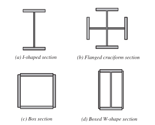
I was flipping through 358-16 last night to check out some of Deker's references. One thing that I noticed was that they've extended pre-qualification to some of the more exotic column shapes. Built up box columns, cruciform I-shapes, etc. Interestingly, the decision to include these shapes was based on judgment rather than testing. To paraphrase the reasoning:

Meh. So long as the inelastic hinging happens in the the beams, may the columns aren't such a big deal after all.

So I guess there's still engineering judgement at work on the west coast after all. It's just concentrated in the hands of the hyper-qualified/pre-qualified.

Capture_ihcbg5.png


I like to debate structural engineering theory -- a lot. If I challenge you on something, know that I'm doing so because I respect your opinion enough to either change it or adopt it.
 
Status
Not open for further replies.
Back
Top