Eng-Tips is the largest engineering community on the Internet

Intelligent Work Forums for Engineering Professionals

X-Braces with Central Node Moved Upward - 6

Status
Not open for further replies.

Cpw628

Structural
Jan 18, 2024
8
0
0
IS
I came across the article "Evolution of the Braced Tube" by Structure Magazine that shows the 800 Fulton Market in Chicago as having an X brace with the center of the X shifted up. The article states that when the members are deflection controlled this is more efficient, but doesn't get into why. I made a model and included some screenshots from it, but am having a hard time understanding why and what shifting the node does. I'd also imagine that this significantly reduces the ductility of the structure if one of those braces buckle.

See page 46 of the June 2024 edition of the Structure Magazine.
Link

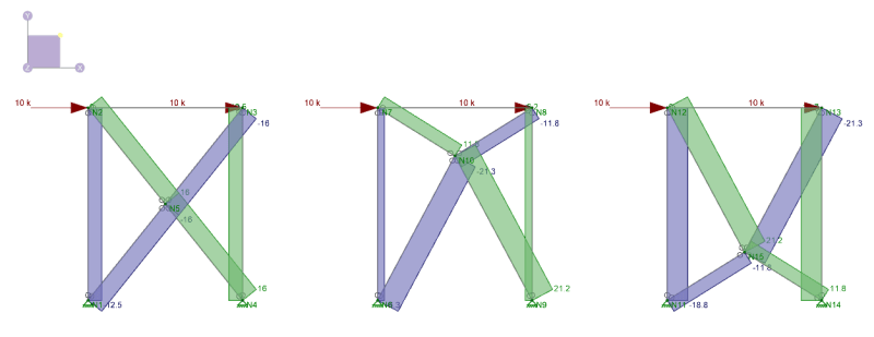
Axial forces in braces:
Screenshot_2024-07-23_174508_yt3gex.png


Deflections in all 3 braces at the top left corner of brace:
Screenshot_2024-07-23_174854_qagvva.png


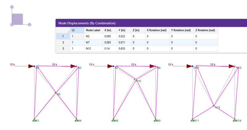
Image of 800 Fulton Market:
Screenshot_2024-07-23_173034_lvvaie.png
 
Replies continue below

Recommended for you

I ran the analysis out of curiosity. Are you sure both readings should be 0.085? I see different number when I move the node up (or down). Also, why does your lateral displacement change when moving the node down but not when you move it up?

For a single-storey structure, my result shows moving the node up increases deflection. However, in multi-storey structure, the offset nodes result in slightly less deflection. However, making the braces tension-only makes the offset node case worse. The actual building appears to use a single X-structure forming a flat pyramid designed to change in "height", so presumably the real effects are quite complex.
 
@Tomfh I think that OP just put in the load that's not high enough to notice the difference. The differences that I got were not that high (I tried moving the joint from h/2 to 1/3 h and 2/3 h).
It depends on the exact geometry I guess and also did you put a concentrated force in one node or distribute it along the horizontal element.

Interesting that you got the opposite of what I got. By my analysis (all elements are of exactly the same section, h/L = 1 and all elements are axial load only) the stiffest one is the one that can be seen in the photo from the original post, even when I placed 3 stories I got the same result.

This kind of makes sense to me - the diagonals follow the stress flow (trajectories) more closely. If you had a wall stresses would "like" to flow in that type of shape. If you now have to remove the material from that shell, it will retain the most of its stiffness if you remove the parts in a way that follows stress flow most "naturally".
 
hardbutmild said:
This kind of makes sense to me - the diagonals follow the stress flow (trajectories) more closely. If you had a wall stresses would "like" to flow in that type of shape. If you now have to remove the material from that shell, it will retain the most of its stiffness if you remove the parts in a way that follows stress flow most "naturally".

For a visual representation of this comment:

temp_vgdkdh.png
 
Hardbutmild said:
Interesting that you got the opposite of what I got. By my analysis (all elements are of exactly the same section, h/L = 1 and all elements are axial load only)

Interesting. I’ll check again.

I did H/L = 4/3, and I used smaller members for the braces than for the columns.
 
JLNJ said:
On first blush, it seems that out-of-plane buckling would be an issue.
I checked, if you move the point to 2/3 H instead of 0,5 H you get 12,5 % larger compressive force in the bottom part of the diagonal (buckling length is also 12,5 % larger). That is about 25 % smaller critical load and 12,5 % larger force for the long diagonal than in the case of a regular X. Top part of the diagonal (not that it matters much) has 10 % less force and is 10 % shorter.
Note that I checked this for a specific H/L and joint loaction, it's probably different in different cases, but just for a rough estimate.
 
What braces the intersecting node? In a traditional x-brace testing has shown that the tension arm "braces" the compression arm at the middle node. Or, you could design the members for full-length compression instead of half-length. With the "kink" in the middle, the action is not so obvious.
 
JLNJ said:
What braces the intersecting node? In a traditional x-brace testing has shown that the tension arm "braces" the compression arm at the middle node.
Same thing for a non-traditional brace I feel like. It's the tension element that does the bracing as far as I understand it and that element exists in both systems.
 
human909 said:
For a visual representation of this comment:
Thank you! This made the most sense.

hardbutmild said:
Same thing for a non-traditional brace I feel like. It's the tension element that does the bracing as far as I understand it and that element exists in both systems.
Agreed, the article states this as well. I recommend giving it a read. They mention that it is not the design to pick if you are controlled by buckling, but mainly controlled by deflection.

Another interesting thing about the article is the middle node is designed to accommodate differences in concrete creep of the main columns and the rigidity of the steel braces.

 
I don't believe that the modeling below or the theory behind it is the answer here. Those stress trajectories are as they are because the model involves a setup where the wall panel has moment at the bottom and not at the top. Any analogous wall in the upper third of a tall building will be a significantly different animal.

1_ksxmtw.png
 
Thanks for your input Kootk. Overall my gut agrees with you.

However, my current bandwidth for deep analysis and discussion is pretty low at I'm working 12hr days at the moment (it is 530AM here). So I'm going to sit on the fence regarding the analysis and the deeper understanding. I am still surprised by the suggestion that this configuration is stiffer, but I haven't pulled on that thread enough at the moment.

Regarding that FEA picture. I just whipped up that model to visualise for myself and others what hardbutmild was talking about. That said, I will still play devils advocate here on one point:

KootK said:
I don't believe that the modeling below or the theory behind it is the answer here. Those stress trajectories are as they are because the model involves a setup where the wall panel has moment at the bottom and not at the top. Any analogous wall in the upper third of a tall building will be a significantly different animal.
From the perspective of the bracing is it not correct that the top corners experience lateral loads and that the bottom corners are fixed? Isn't that what my FEA model shows?
 
My gut feeling - the shallower angle braces near the top have a smaller vertical component of force as compared to a true X. Thus the axial elongation is lower and the "flexural" displacement is smaller. This is of course means the loads in the lower steep braces go us, so "shear" displacement would go up. In a deflection controlled structure, the flexural component is likely to be more critical, since if you are so stiff that shear deformations are controlling you likely are meeting deflection criteria,

Untitled_r4qha1.png
 
human said:
From the perspective of the bracing is it not correct that the top corners experience lateral loads and that the bottom corners are fixed? Isn't that what my FEA model shows?
I think that KootK was aiming at the fact that in tall buildings frames hold walls at the top third of the height and vice versa at the bottom. This means that the wall is not really a cantilever but it's kind of propped at the top third by the frame action.
I tend to forget that since I don't do any tall buildings, but I think the mechanism that I was talking about works for low and midrise buildings.
I can't really follow your theory KootK, I feel like I'm not smart enough to get it. "Lamellar slip" is a bit too complex for my level. :)
 
I'm kind of warming up to the wall principle stress trajectory thing. Even if that's not the entirety of the loading on the panel, it's a component of the loading on the panel. Any maybe that's enough.
 
There’s an increased use of topology optimization nowadays. I think companies like TT and Arup have developed in-house algorithms. Pretty cool stuff.

IMG_5920_i26uko.png
 
Status
Not open for further replies.
Back
Top