Continue to Site

Eng-Tips is the largest engineering community on the Internet

Intelligent Work Forums for Engineering Professionals

  • Congratulations waross on being selected by the Eng-Tips community for having the most helpful posts in the forums last week. Way to Go!

Yield line method VS finite element for flat slabs 7

Status
Not open for further replies.

Gus14

Civil/Environmental
Mar 21, 2020
186
Quoting the practical yield line design book published by the concrete center, " flat slabs on a rectangular grid of columns are essentially one-way continuous slabs in two directions and as such are analyzed and designed separately in both directions. "

I found their example a bit confusing, as they only studied one direction,
Did they ignore the other direction due to symmetry? as the same moments will occur in the other direction

I studied two models of flat slabs. Model 1, yield line moment results were about 10 percent larger than the finite element results.

Model 1,
In model 2, yield line moment results were about 15 percent larger than the finite element results.

Model 2,
Am I applying the yield line method correctly?

*Sidenotes:
1. Regarding top reinforcement, I understand that a middle strip will attract some of the moments. I ignored it to be more conservative for the column strip. The middle strip reinforcement will be provided appropriately later.

2. I assumed 0.35 * the positive moment along the slab edges because simple support is impossible to achieve. The columns will attract negative moments, as observed in the finite element model.
 
Replies continue below

Recommended for you

It cannot approach solutions reliably from any side as it is based on fudge factors ("column strips" and "middle strips") and representing a two-dimensional plate-type structure as a collection of orthogonal beams. The fact that it has been used with some success can mostly be attributed to the fact that for regular layouts of slabs supported by e.g., walls, the twisting moment is not always significant and the concrete design itself involves a lot of safety factors (dividing compressive strength by 1.5 tells quite a lot about the confidence that researchers have in the material properties of your typical slab).

As I mentioned previously, the strip method is convenient for frame analysis conducted independently in two directions. This was the primary method of designing ordinary buildings for most of the 20th century, so it is not a surprise that the method caught on. A more sophisticated analysis would make use of plate element FEM solutions (linear or non-linear) coupled with orthogonal reinforcement determined by e.g., the Wood-Armer method.

ThomasH said:
As for the Finite Element Method, I did a quick Google search and one of the first hits was a text starting with "It is well known that the finite element method (FEM) provides a lower bound in energy norm for the exact solution to elasticity problems." I can't say that I am too surprised and I won't go into any indepth discussion about this smile.
The lower bound in the energy norm refers to the fact the weighted residual with Galerkin choice of basis functions leads to a "best solution" in the space of available solutions. It does not mean that the solution is exact, or that it approaches the solution from the safe side. The fact that FEM approaches solutions from the unsafe side can be found in most textbooks describing the FEM.

PS. On page 149 of the paper you quoted, it is said that "The strain energy from the FEM solution....is a lower bound for the exact strain energy". What this means is that strain energy is underestimated, or in other words: the stiffness of the structure is overestimated (Kd = f --> d = f*(K^-1) --> underestimated stiffness K (containing strain energy of the rod/beam/plate/shell/solid) causes a small divisor which leads to small nodal solution "d") and deflections are underestimated.
 
CentonDollar,

A few points from an old fashioned strip method designer,

- Interesting that the using 2D Frames in both directions results in exactly the same result as FEM for the total panel moments and shears for a regular column grid, if it is such an inaccurate method! The only difference is the distribution across the width which is easily handled with column/middle strips. It fully accounts for Mxy in these cases.

- I see are from Florida, the land of PT using banded /Distributed PT layouts in flat slabs and beams with unlimited flange widths. Seeing you comment on PT and FEM so much I assume it is these types of slabs you are designing. If so

-- How do you justify using FEM analysis results to design using the US banded/distributed PT method? It is a strip design method, based on FEM results, considering it could only possibly be justified using Yield Line Analysis. It "works" with regular column grids for ultimate capacity as a one way strip system. But FEM should never be used for these slabs designed by this method for irregular grids as the FEM analysis is completely unrelated to the reality of the design method which is pseudo Yield Line without actually calculating it properly.

-- How do you justify full panel width design rather than concentration into effective strips, for flat slabs as well and bream and slab systems?

-- How do you justify assuming tendons in slabs between beams to be effective reinforcement in the beams.

-- How do you justify the normal USA logic of ignoring Mxy moments in design of PT slabs

-- How do you justify concentrated loads on column lines being resisted by tendons and reinforcing in the middle of the middle strip?

-- How do you justify using a banded/distributed tendon system with drop panels assuming the full T section in both directions for all tendons?

or do you design differently to everyone else there?
 
centondollar said:
PS. On page 149 of the paper you quoted, it is said that "The strain energy from the FEM solution....is a lower bound for the exact strain energy". What this means is that strain energy is underestimated, or in other words: the stiffness of the structure is overestimated (Kd = f --> d = f*(K^-1) --> underestimated stiffness K (containing strain energy of the rod/beam/plate/shell/solid) causes a small divisor which leads to small nodal solution "d") and deflections are underestimated.
Correction:
(Kd = f --> d = f/K --> overestimated stiffness K means that nodal variables "d" (e.g., displacements) approach the exact value "from below").

This can be confirmed by e.g., considering a beam with a small amount of elements and more or less regular load and boundary conditions: as element size is reduced (and more nodal variables to be solved appear in the linear equation system Kd=f), the difference (measured in e.g., area below the axis of bending) of "exact" and "approximate" deflection fields is reduced. In other words: the interpolation of smooth fields of primary problem variables (displacement and rotation, or temperature, or pressure etc.) with polynomials introduces an artificial stiffness to the FEM solution usually to be mitigated by reducing element size.
 
The lower bound theorem has a specific meaning in English structural engineering jargon, being the sense that ThomasH is using. Link below. The strip method fits into this. FEM doesn't always - depends on whether the solution satisfies equilibrium.


(I only read the first few paragraphs)

Rapt, I would say Centondollar is in Finland given s/he seems to be European, and feel confident in saying s/he does not subscribe to American abominable design methods.
 
rapt said:
- Interesting that the using 2D Frames in both directions results in exactly the same result as FEM for the total panel moments and shears for a regular column grid, if it is such an inaccurate method! The only difference is the distribution across the width which is easily handled with column/middle strips. It fully accounts for Mxy in these cases.
As the aspect ratio of a slab gets smaller, the influence of twisting moments increases. I understand using yield line theory to produce an orthogonal bending moment distribution (Mxx, Myy) acting at yield lines, but ignoring twisting by referring to "column strips" and "middle strips" is - as far as I know - ad-hoc and not something one can derive from mechanics. Correct me if I am wrong.

rapt said:
-- How do you justify using FEM analysis results to design using the US banded/distributed PT method? It is a strip design method, based on FEM results, considering it could only possibly be justified using Yield Line Analysis. It "works" with regular column grids for ultimate capacity as a one way strip system. But FEM should never be used for these slabs designed by this method for irregular grids as the FEM analysis is completely unrelated to the reality of the design method which is pseudo Yield Line without actually calculating it properly.
Load will be attracted to where there is stiffness. Prestressing in one direction with some sort of characteristic "longer" span (e.g., short span between two walls or long span with walls at the short ends) can be done by considering the slab as a "wide beam" in such cases.

rapt said:
-- How do you justify full panel width design rather than concentration into effective strips, for flat slabs as well and bream and slab systems?
There is no "effective width" in a flat slab in bending, so I don't understand your concern. Please elaborate. Regarding beam and slab systems, e.g., T-beams, those are usually designed by using an effective width of the flange due to shear lag.

rapt said:
-- How do you justify assuming tendons in slabs between beams to be effective reinforcement in the beams.
If rebar fits into the effective width of the T-beam flange, it is at least partially effective in the T-beam assembly. Regarding tendons in a slab between beams, I've not seen that before; prestressing the beam is what I've encountered.

rapt said:
-- How do you justify the normal USA logic of ignoring Mxy moments in design of PT slabs
As far as I know, accounting for Mxy is not uncommon in the US. I've read technical notes about it in Structure magazine, software manuals and US engineering journals.

rapt said:
-- How do you justify concentrated loads on column lines being resisted by tendons and reinforcing in the middle of the middle strip?
Unless there is a T-beam action (with effective width extending into "middle strip") involved, I wouldn't expect tendons or reinforcement located far away from load application to resist all applied load.

rapt said:
-- How do you justify using a banded/distributed tendon system with drop panels assuming the full T section in both directions for all tendons?
I don't, and as far as I know, prestressing in two directions and calculating the effects with the simple beam relations (stress = M/W + P/A) does not produce reliable results. For such design, consideration should be given to how the two-way precompression distributes into concrete. I would much prefer to prestress only in one direction for slabs and T-beams with an aspect ratio large enough to produce "beam"-type flexural behaviour. It may not be state of the art, but I'll gladly leave fancy prestressing to fearless engineers with a strong gut.

PS. I do not practice engineering in Florida.
 
I have checked the material I have regarding the strip method and it originates från Arne Hillerborg. The original theory comes from a text called "Equilibrium theory for reinforced concrete slabs". One issue is that there is not a lot published in english by Hillerborg which has resulted in some misunderstandings. But there is a PhD thesis by Crawford from 1962 that analyzes and discusses yield line theory and equilibrium theory (expecially strip method). There seem to have been a lot of developments in this and Hillerborg did not agree with all of them.

I see an obvious risk that my "version" of the strip method and the version refered to by others differ. But Hillerborgs original idea was that the slab should be in equilibrium.

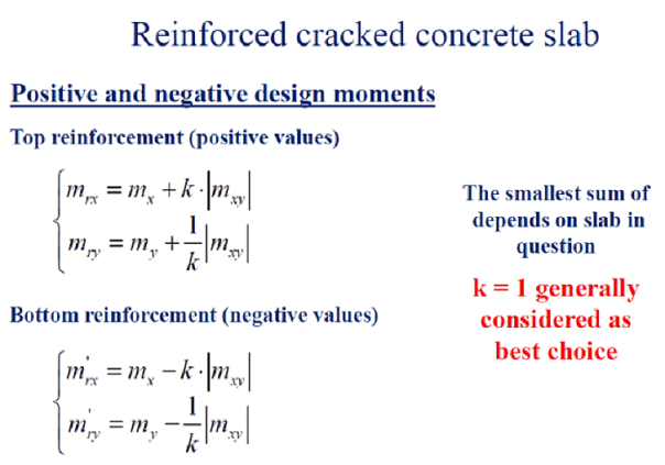
@centondollar, you mentioned a more "sophisticated" approach with FEM and adding the twisting moments according to Wood-Armer. When I Googled that I got the following:
Temp_jkrmyp.png


I have to admit that I was a bit surprised by that result because I have used it many times. But I have never heard the reference "Wood-Armer" before in that context. I have only considered it as a simple and conservative method to include the twisting moment is a slab solution.

Finally: I am in Europe but I have been on the forum long enough to recognize a lot of the mentioned methods. I have also done projects both in the US and of course in Europe. My preferred method for designing a slab would be FEM. It is not perfect but it is probably the best and most general tool we have available today. Especially when working with non-linear problems FEM can be a very helpful toll. And even if the codes vary in different countries the laws of nature doesn't [smile].
 
CentonDollar,

Referring to column and middle strips is not ignoring Mxy moments.

The total moment from an equivalent frame analysis for a frame panel in each direction is the same as the total moment, including Mxy, from an FEM analysis. Designers using FEM for analysis and then ignoring Mxy (which at least used to be the default setting in some major US software) in design results in under-design.

Designing a flat slab to an FEM result will always be based on effective strips. The absolute peak moment is never designed for, it is always averaged over a width. For UDL loadings, the maximum strip width over supports should be the column strip width. For concentrated loads, smaller strip widths should be used depending on the situation. ACI-318 ignores this.

From all of your answers, it is obvious that you are not conversant with the design methods used in USA based on ACI/PTI logic. The list above are assumptions made commonly in design practice to ACI-318.

My main problem is with designers doing a FEM analysis and then not reinforcing to the pattern of the FEM result, thus requiring large redistributions of actions to make the structure work, without accounting for the effects. They are often using a design that can only be justified by yield line theory based on a completely unrelated FEM analysis without understanding the limitations.
 
Status
Not open for further replies.

Part and Inventory Search

Sponsor