Eng-Tips is the largest engineering community on the Internet

Intelligent Work Forums for Engineering Professionals

  • Congratulations waross on being selected by the Tek-Tips community for having the most helpful posts in the forums last week. Way to Go!

Z Purlin Compression Strength 1

Status
Not open for further replies.

LSUengr2013

Civil/Environmental
Jul 20, 2020
13
0
0
US
My team and I have been contracted to review a PEMB for the installation of some new exhaust fans. These fans are attached to 8" Z-purlins which are through-fastened to an R-panel type metal sheathing.

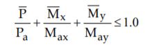
We have been utilizing RISA-3D to conduct the analysis. When running the analysis, the Z-purlins are failing according to AISI code equation H1.2-1 which is combined axial load and bending.

eq_midywp.jpg


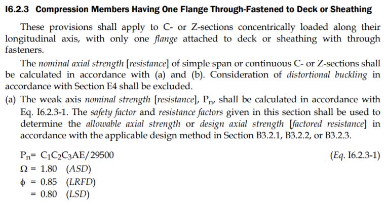
We believe the compression in the purlins is coming from the overall deflection of the main support/girter system and this compressive load is overstressing the member. Reading further into the AISI code, there is a provision for calculation the weak axis compressive strength for a purlin with one flange through fastened to metal sheathing. When we do this calculation by hand, it leads us to a much larger allowable axial compressive force than what RISA is calculating, approximately 7-8x higher. This value also is very close to values found in load tables/charts.

When we insert this hand calculated value into the H1.2-1 equation, the members passes unity. So my question is, could this be a limitation to the programming of RISA and we should rely on our hand calculations for this instance? I do not know of a "factor" within RISA to tell it to default to this equation for allowable axial compression as we are already using Lcomb top, etc.

Any insight into this would be greatly appreciated!
 
Replies continue below

Recommended for you

Wouldn't deflection of a girder put them in tension anyway? I see two solutions, get the purlins out of your model, do a 2d frame analysis on the portal frames, and analyze the purlins as simply supported beams. Or take the forces from RISA and apply the equation yourself as you've done.
 
I'm surprised that you have compression in the purlins from the gravity load of the exhaust fans. I doubt that it's coming from the girder deflection - something else is happening here. I think I would try to find out what's going on in the model first before I delved into the interaction equations.

 
Each z-purlin has a vertical brace down to the bottom flange of the main girter beam. THrough some trial and error, we have determined that these vertical braces on each end of the purlin are introducing compression into the purlins. When you remove these from the analysis, the purlin behaves as expected, in tension.
 
I believe those would be fly-braces (or choose your locale terminology) intended on bracing the moment frames when subjected to uplift. Perhaps it would make sense to detach them during installation to allow the Z-purlin to deflect under the new dead load without the brace at the end fixing up the connection at the end. Then re-connect the brace to the purlin to re-institute the bottom flange bracing for the main girder.
 
We currently are taking P-delta analysis into account in our analysis. Which I guess potentially was most likely not done in the early 80's when this building was constructed.
 
Have you also taken into account any flange strapping/bridging angle on the purlin members? Remember to get your M(subs) from going through the F2, F3, and B3.2.1-2 equations in AISC S100-16 (or equiv). It's not the easiest analysis, but it works. The flange braces you're talking about are used more for bracing the inner flange of the rafters than anything else. I've never used RISA personally, so I can't talk along those aspects.


I think you are referring to AISI equation D6.1.3-1 (in the 2012 version). It doesn't appear that RISA has an option to include this. The Lcomp top you mention is for beam buckling and not column buckling. If you temporarily set Lbyy in RISA to the deck fastener spacing (I would use 12" based on AISI footnote #8 in that section) and you still get an allowable compression value less than what that AISI equation gives, then I think something is wrong. You would need to change Lby back to the full member length in RISA afterwards since that is not accurate for this case and assumes normal bracing for weak axis buckling and not some hybrid like AISI appears to be presenting. I would then feel more comfortable using the AISC formula and not what RISA is currently giving you if you meet all of AISI's criteria to use it.
 
haynewp said:
If you temporarily set Lbyy in RISA to the deck fastener spacing (I would use 12" based on AISI footnote #8 in that section) and you still get an allowable compression value less than what that AISI equation gives, then I think something is wrong

We changed the Lbyy criteria to 12" and got literally no change in the allowable compressive strength. It still equates to around 1.3 kips. No matter what we change the Lbyy to, that value doesn't change.

When we use the section shown below, the allowable comes out to be around 9.8 kips.

Capture_ssc81w.jpg


We have struts at third points across our 25' span, so we are using an Lbyy value of 8.33. When we run the analysis through RISA the unity check gives 1.1, but using the 9.8 kip allowable in the H1.2-1 equation gives us a unity of .80.
 
Doesn't make much sense. Would you mind removing any project identifying information and post the model? I am kind of interested in what is going on as we have a similar project upcoming with new mech and a lot of above roof duct supports going on an old PEMB.
 
The only other idea I have is that restraint also assists in bracing for torque (torsional mode) buckling. It all seems like a stretch especially if it wasn't based on testing.
 
Status
Not open for further replies.
Back
Top