Eng-Tips is the largest engineering community on the Internet

Intelligent Work Forums for Engineering Professionals

Zero-Cross detect circuit

Status
Not open for further replies.

Moonwalker031

Electrical
Jun 5, 2010
33
0
0
MT
I am using a Triac dimmer for dimming an LED (dimmable) lamp. The zero-cross detector is from a simple transistor on the secondary of the transformer (before smoothing). All works fine except that the LED flickers a bit in the low range. Analyzing on the scope the zero-cross pulses vary in the range of 50us between cycles and this is enough to vary the brightness of the LED lamp at the low voltage ranges.
I have tried this circuit - but still got same error in the pulses.
With incandescent lamp this problem is not visible as the lamp has not enough time to turn off from cycle to cycle.

Is this normal to have such error on mains frequency? And is there any way to solve this?
 
Replies continue below

Recommended for you

What's your circuit?

The mains frequency doesn't change at all. However there could easily be harmonic distortion on it. Have you looked at it with a scope?
[!]BEWARE looking at the mains with a mains powered scope is non-trivial.[/!] Read up on it before attempting it.

Keith Cress
kcress -
 
zerocross_l0kq7z.jpg


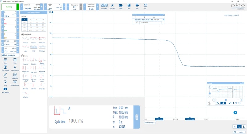
Here is a test using this circuit - I have increased the input capacitor to 10nF and added a dual coil filter on the input but still getting around 50us between cycles. I don't have an isolated probe to show the input sinewave at the same time.
I do have harmonic distortion from the Inverter Air-conditioner but with the added filtering it is not making much difference.

The scope image shows the cycle time which varies from 9.71ms to 10.03ms. The main image shows the falling edge of the second pulse which varies continuously between the rulers.
 
zerocross2_jps5lx.jpg
zerocross3_lq0td1.jpg


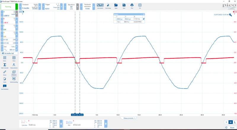
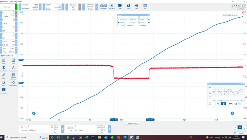
Ok managed to capture input sinewave (through 3 series 100k resistors and measuring on the middle one = 1/3 voltage) and output pulses at the same time.
Sinewave does not look very good so probably its the harmonics that are messing with the timing.
Zooming on the pulse rise/fall time the variation is happening in sync with the variations of the input sinewave. Even setting probe with 200Hz filter it is still not stable enough.
 
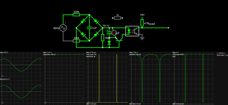
in my simulations, the duty cycle was not narrow enough 12%. To improve this greatly to 1 to 2% and thus reduce low-level Triac phase and jitter;

1. Change load R2 from 22k to 100k . This is essential to cut the duty cycle in half. This may be enough but for more reduction in duty cycle keep reading.
2. Put a RED LED across C1. This reduces the width of the charge pulse and also the Cap voltage to about <=1.5V with low charge current and not illuminated but also reduces the ripple and cuts the base current duty cycle to 1% That may work.
3. Pulse spreading then occurs to 2% with a medium hFE 2N3904. A high hFE 2N5088 or PN2222A will boost the current but not lower the voltage much since the D.F. is now 1% The current limiting resistor, R4 is now redundant and may be bypassed as the LED limits the Opto diode current.

This should result in 20 us pulses.

I prefer to use an XOR gate from a line freq square wave with one leg delayed by T=RC with leading-edge in sync, but you may want a symmetric pulse.


Clipboard02_yyazhj.jpg
 
Status
Not open for further replies.
Back
Top