Eng-Tips is the largest engineering community on the Internet

Intelligent Work Forums for Engineering Professionals

  • Congratulations waross on being selected by the Eng-Tips community for having the most helpful posts in the forums last week. Way to Go!

RC Beam with Set down Analysis and Detailing 3

Status
Not open for further replies.

ENGUCR

Structural
Sep 23, 2017
37
LK
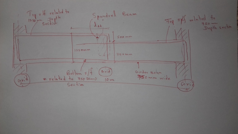
For a heavily loaded power station, A girder beam having a 500 mm set down is required to design(refer attachment). This girder is also supporting spandrel beam exactly at the set down location. The design procedure that I have followed for this non prismatic beam is as follows
1. The beam is modeled using frame element as a sub frame.
2. Two different frame elements are defined for the different two sections and they are combined using insertion points & thereafter loaded the beam
3. Analysis results are obtained and the bottom flexure r/f are derived using the 750 mm(D) dropped section & continue through out the bottom
4. Top r/f at restraint ends are also calculated for respective sections(1250 and 750 mm D)
5. Links are calculated from the analysis results at both ends for respective sections while provisions are made for the hanger links also
6. The Detailing is done as given in the attachment

Please comment if there are any more considerations on analyzing, designing and detailing to be done for these kind of beam sections
Thanks in advance
20171029_082803_zpt7ko.jpg
 
Replies continue below

Recommended for you

I would analyse it as a simple span for your bottom reinforcement.
 
Yup, with Hokie, and your top bars don't need such long hooks... they don't help in compression.

Dik
 
@hokie66
I have to use maximum available ways to control deflection. Client has imposed a deflection control criteria. So the column fixity need to be considered. Simply supported would end up in some what deep sections which also rectrict head room.
@dik
No the top bar does not extend such extent. It would curtail at PoC. It was drawn extendedly for the easilyness. I would like to know whether any additional consideration to be followed specially at the 500 mm dropped section
 
If deflections are critical, are you doing a detailed deflection analysis, taking account of cracked section properties and creep and shrinkage effects?

Doug Jenkins
Interactive Design Services
 
@IDS
Yes of course. Long term deflection is also considered. Deflection is reduced by means of the column fixity
 
Your compression reinforcing will help a lot.

Dik
 
1) How wide are your columns? Based on the proportions that you've shown graphically, I'd be inclined to follow Hokie's advice and treat the beam as pinned. As shown, it's hard to imagine that the stiffness of the columns would add much to deflection control and the joint detailing may be problematic.

2) Given that you're pursuing end fixity of sorts, I question whether it's appropriate to utilize compression reinforcement for deflection control here. The most critical locations for that reinforcement would be the bottom steel at the ends and the top steel in the middle. Your bottom steel at the ends may be ineffective unless you can develop those bars into the columns in straight compression development. And your top steel at mid-span will be partially compromised by the fact that you're passing the compression across a 500mm step which means that your compression is back in the concrete for a spell there. All tolled, that would be too much uncertainty for me to feel comfortable relying on compression steel.

3) In any detailed deflection analysis, I would model the step as though it occured 1000mm to the left of where it will actually be located. It takes some distance for the compression force in the beam to shift across the vertical offset and, in my opinion, one needs to take account of that to avoid underestimating the contribution to flexural strain there.

4) At the step, you have not said anything about how far the top bars in the shallow section will be extended into the deep section. I'd want that to be at least compression lap length + 1.5 x 500.

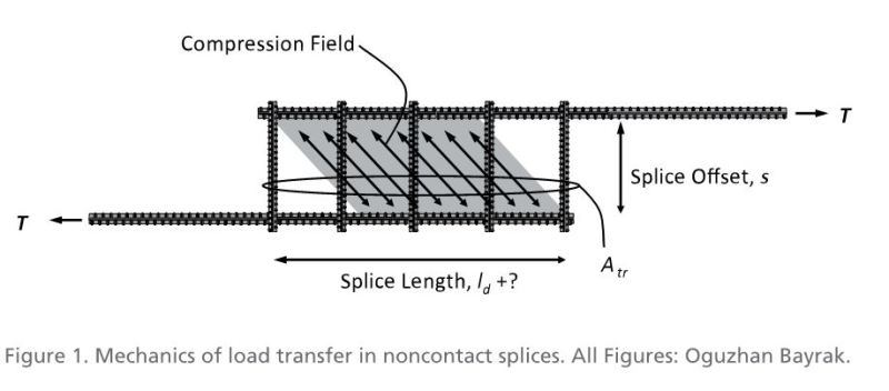
5) At the step, you will pass the compression force in the top steel across the 500 mm step. That, effectively, is a non-contact lap splice which will create a local demand for link reinforcing that you haven't mentioned. See the sketch below but imagine the rebar in compression rather than tension.

C01_gq4oz9.jpg


I like to debate structural engineering theory -- a lot. If I challenge you on something, know that I'm doing so because I respect your opinion enough to either change it or adopt it.
 
STENG456,
It would be of interest to know the details of the client specified deflection control criteria.
 
Does the flange fully engage with the support as well or is it free to rotate away from the support. If the later you should use an equivalent column stiffness to allow for the torsional rotation of the flange away from the support.

Agree that due to shear lag, you should not consider a vertical step. either 45 degree slope or 30 degree depending on who you listen to. Most designers ignore this.

The very top bar will have no compression effect where it is needed most, where it starts near midspan as it develops nothing in compression from the downward bent leg. Building up to full compression capacity at a development length from the step.

The compression reinforcement is not needed near the ends as much so no worries there.

Hanging shear reinforcement will be needed for the beam supported on the side face in addition to your normal shear reinforcement requirements.

You have not nominated bar sizes. How big are they. Can sensible bends be achieved?

IDS's question was asking if you were doing a detailed crepp, shrinkage, cracking, tension stiffening analysis, or using a multiplied approach and Branson,s formula.
 
@KOOTK-Thanks
1. Column dimensions are 500 mm Deep(in plane)x750 mm wide (out of plane). F2F height nearly 3.8 m. This sizing would induce some fixity.
2. I won't utilize compression reinforcement for deflection control. I haven't made such a statement. The beam is just singly reinforced section. Strength is controlled by only tensile yielding. The mid span top bars are just link hangers. But the top bars at column are to cater flexure induced by the fixity. It's just simple. When there is column fixity present at support location, deflection is reduced in compared with a pinned connection. Simple sub frame with columns
3. Helpful
4. Just hangers at the mid span. Nominal anchorage would be provided in to the deep section
5. Helpful. But this will only required if the top bars are in compression. Is n't it???

Apart from that I have seen some designers uses very close spacing of links in the vicinity of the step(To both left and right). Is it required??? What would be the reason behind it??

@hokie66
It's 20 mm or L/350 whichever less. Long term

@dik
Thanks. Hope these are only required when the top bars in compression. I am performing a detailed creep and shrinkage analysis for the deflection analysis

@rapt-Thanks
The flanges are fully engaged. The vertical step can't be ignored as the clear 500 mm is required beyond the step and the 1250mm segment will support the upper slabs and secondary beams. Link Hangers will be provided
The bottom bars will be 7H25 and Top bars at column ends are also 7H25. The Links hangers are out of from 7H16 bars


Would it be possible to just analyze the beam as 750 deep, the extra 500 would just be additional loading. That would still result in a fairly stiff beam.
 
OP said:
This sizing would induce some fixity.

Agreed.

OP said:
I won't utilize compression reinforcement for deflection control. I haven't made such a statement.

Granted. It's the internet. Sometimes we have to attempt to read between the lines.

OP said:
Just hangers at the mid span. Nominal anchorage would be provided in to the deep section

Fair enough if you're not using the top bars as compression steel.

OP said:
But this will only required if the top bars are in compression. Is n't it???

You'll have a different version of the same problem if the top bars are not used in compression. The compression force in the top of your beam on the deeper side will need to be "turned" diagonally as it dives down to meet the compression force in the top of the shallower beam segment. That "turning" at the knuckle will produce a tendency to pop out the concrete at the change in direction of the strut. This can create a demand for links locally at the high end of the diagonal strut. I don't know that there's a matching demand at the low side of the diagonal strut so long as shear has been properly designed for there.

I like to debate structural engineering theory -- a lot. If I challenge you on something, know that I'm doing so because I respect your opinion enough to either change it or adopt it.
 
KootK:
The beam will function well without diagonal bars. The shallower portion is about 1/5 the stiffness of the deeper section... The top bars do little, except add to the stiffness for long term deflection and creep resistance.

Dik
 
jayrod12 said:
[/Would it be possible to just analyse the beam as 750 deep, the extra 500 would just be additional loading. That would still result in a fairly stiff beam]
Deflection control is the major issue here. Heavily loaded girder beam(LL=7.5kN/m2) with 10 m span. I have to utilize every inch whatever it gives in advantage against deflection control. So 1250 mm Deep section is lot to me. I have tried your way, But it failed in deflection
 
dik said:
The beam will function well without diagonal bars.

I didn't suggest diagonal bars dik. In my last post, I was discussing diagonal compression fields.

I like to debate structural engineering theory -- a lot. If I challenge you on something, know that I'm doing so because I respect your opinion enough to either change it or adopt it.
 
No sweat. Sometimes we all cajole the words that we read into suiting the pictures we have in our heads.

I drew this scenario to scale for curiosity's sake and have the following additional observations:

- I can see why there might be deflection problems. The beam is pretty slender.

- I'm reverting back to the conclusion that the columns probably don't add much stiffness here. Proportionally, it just doesn't jive for me unless these are abnormally short columns.

- Because I don't feel that the columns will add much stiffness, I believe that jayrod's proposal for treating it as a faux shallow beam may well make a lot of sense here. The thing will be behave quite a bit like a simple span beam with the right half being pretty rigid body like and the deflection being largely a function of what's going on with the right, shallow half. It may well be that deflection isn't too far off of what it would be if you treated the member as shallow the whole way across. Especially since you'll be shifting the step to the left 1000 mm or so for your analytical model.

I like to debate structural engineering theory -- a lot. If I challenge you on something, know that I'm doing so because I respect your opinion enough to either change it or adopt it.
 
And a bonus with my plan, you can use the compression steel in your long term calculation!
 
Status
Not open for further replies.

Part and Inventory Search

Sponsor

Back
Top