Continue to Site

Eng-Tips is the largest engineering community on the Internet

Intelligent Work Forums for Engineering Professionals

  • Congratulations KootK on being selected by the Eng-Tips community for having the most helpful posts in the forums last week. Way to Go!

Shear Lag in Tension Plate

Status
Not open for further replies.

JAE

Structural
Jun 27, 2000
15,447
If you have a long plate (Plate 1) that is in tension, with a force of Pu (factored) and you need to occasionally have a splice in it to limit the length of plates needed in the field, and if you used a perpendicular splice plate as shown in the attached image, how would you treat the issue of shear lag in the splice Plate 2?
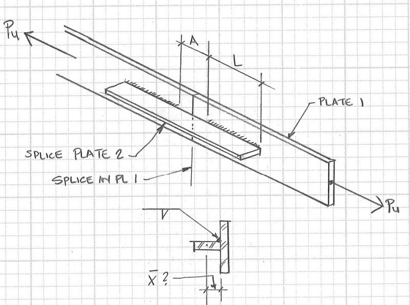
Splice_Plate_xoroaw.jpg

AISC has table D3.1, which provides various U values to reduce the effective area of the plate when checking a plate's tension capacity.

This takes the form of ΦPn = ΦAe(Fy)U.

However, table D3.1 doesn't seem to include this particular condition.
Case 2, which includes the U = 1 - x/L specifically omits plates.
Case 3 is for transverse welds, not longitudinal.
Case 4 seems to apply to a plate with longitudinal welds on both sides of the plate – not on just one side.
The other cases are all totally different conditions.

Any thoughts?


Check out Eng-Tips Forum's Policies here:
faq731-376
 
Replies continue below

Recommended for you

I think you could make the argument that Case 1 could be used, but I would look at Case 4 (Plates where the tension load is transmitted by longitudinal welds only). There are stipulations in Case 4 that lower U=1 to either U=0.85 or U=0.75.
 
JAE said:
Case 2, which includes the U = 1 - x/L specifically omits plates.

JAE,

The 15th edition of the manual doesn't mention that plates are omitted.

Depending on dimensions you could have significant reduction if your splice length is short compared to the width od the splice plate.

Also, I'd check block shear rupture on those main tension members.

 
laying pl 2 flat against pl 1 would be a much better splice....there is a large amount of eccentricity in the splice as shown......
 
I think using U=1-xbar/L is a reasonable approach, with xbar equal to half the plate width like you show. You could also check the plate for combined moment and tension, where the moment is the force times half the plate width. With any luck the two methods will yield about the same results.

I also agree that turning this plate flat against plate 1 would be a better splice. (Might your sketch be a simplification of something larger?)
 
I forgot to mention that we can't turn the plate flat for reasons not in the sketch. Weld access limits that.


Check out Eng-Tips Forum's Policies here:
faq731-376
 
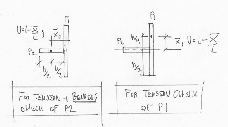
I believe that it should be as I've illustrated below and that a check is required for both P1 & P2. There are three ways to get there. Using P1 as an example:

1) Case 6a with H collapsing to zero
2) Case 4 with W = P1 width
3) Case 2 recognizing that x_bar here is about vertical load spread, not horizontal.

It makes sense that there is convergence since all three cases are adaptations of the same fundamental concept. The key feature of all three, taken in this context, is that you're delivering a load that is concentric about both axes but needs to spread out in the vertical axis.

Key to this is recognizing that the flexural strength and stiffness of P2 is what enables the load to be considered to be delivered to P1 concentrically. As such, Nutte's recommendation of a combined stress check for the splice plate is important.

c01_wrlbge.jpg


I like to debate structural engineering theory -- a lot. If I challenge you on something, know that I'm doing so because I respect your opinion enough to either change it or adopt it.
 
I know I'm saying nothing you don't know, but that's one ugly splice !

Agree with KootK, certainly the splice plate in in bending. You could do a "shear lag" analysis for the shear into the splice: I suspect a linear assumption is not too bad. FEA ?

another day in paradise, or is paradise one day closer ?
 
my gut feeling tells me that pl 2 will tend to rotate upwards, if so, not good for that one-sided weld....at the moment, I can not fully state the mechanism involved other than the pl2 will also have some in-plane eccentricity and ,depending on it's thickness, could be insignificant or a concern......
 
Yeah, as a practical matter, I might weld a few topside stiffener plates along the splice to stabilize it against potential rotation.

I like to debate structural engineering theory -- a lot. If I challenge you on something, know that I'm doing so because I respect your opinion enough to either change it or adopt it.
 
if you could I'd weld an opposite to plate 2 ... another "standing" plate on the other side of plate 1 (to keep things balanced. But no doubt you can't. How will this look ? (will plate 2 cause a visible deflection on plate 1 ?)

another day in paradise, or is paradise one day closer ?
 
Any chance of a PJP or CJP welded splice between the plates?
 
Thanks for your replies.

MotorCity - due to the presence of thin material behind the plates, a CJP weld isn't doable.

rb1957 - there is an opposite plate assembly balancing this off but it is separated by a Macomber joist chord between the two. These plates are an attempt to add strength to a Macomber joist along the bottom chord by adding a vertical plate and stitch welding the plate in two locations to the existing chord, which is a weird shape - and thin too.


Check out Eng-Tips Forum's Policies here:
faq731-376
 
Status
Not open for further replies.

Part and Inventory Search

Sponsor