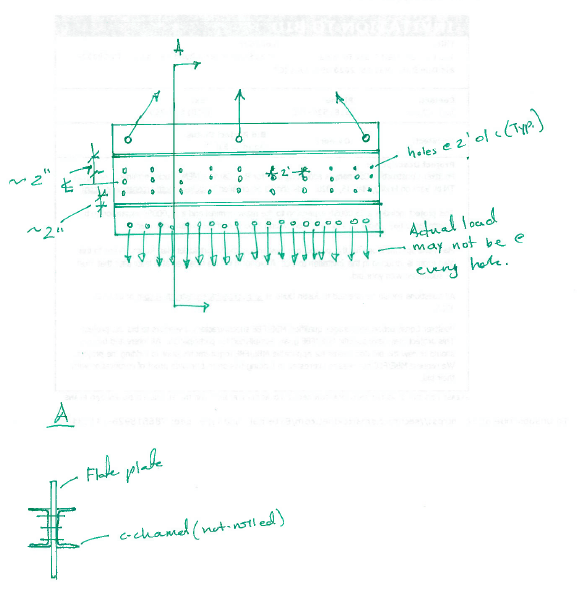
I’m looking into use three beams to make a composite beam to resist moment in the x-axis and also shear. One will be a 1.25” flat plate which will be sandwiched between two C-channels. I was thinking placing three bolts vertically in the web with them being 2’ o/c the length of the beam. Is this generally acceptable? What all design considerations will I need to make on the bolts? How do I ensure it will truly act as one?
Navigation
Install the app
How to install the app on iOS
Follow along with the video below to see how to install our site as a web app on your home screen.
Note: This feature may not be available in some browsers.
More options
Style variation
-
Congratulations cowski on being selected by the Eng-Tips community for having the most helpful posts in the forums last week. Way to Go!
You are using an out of date browser. It may not display this or other websites correctly.
You should upgrade or use an alternative browser.
You should upgrade or use an alternative browser.
Steel Composite Beam Design 3
- Thread starter JP20
- Start date
- Status
- Not open for further replies.
Ganesh Persaud
Structural
You can provide a sketch to further clear up the details of the question.
- Thread starter
- #4
This is similar to the other discussion we had a week or so ago.
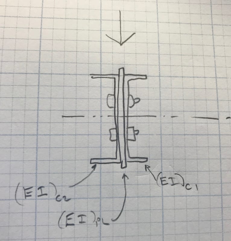
These two channels and the single plate between them simply bend together.
There's no composite action and no shear flow through the bolts to create composite action since the interface planes are all vertical.
The bolts connect the three pieces at a point above or below the NA (per the sketch)and the discrete piece of steel in each section move together with or without the bolts.
In other words:
If you have bolts, the three shapes bend together (assuming load is applied to all three)
If you don't have bolts, the three shapes bend together (assuming load is applied to all three)
The bolts only serve to ensure that the three shapes bend together vertically (same deflected shape downward)
They don't provide resistance to any horizontal shear flow since all three shapes are flexurally independent
Ganesh Persaud
Structural
I don’t see a problem why it can’t be used, you could provide cjp weld from channel to plate. Design considerations, you would need to check the max Plate thickness using AISC manual table 7-6 and then check the bolt group flexural strength. Checks for yielding and rupture, bearing and tear out for both channel and plate. You would also need to check the flexural yield and rupture interactions.
- Thread starter
- #11
JAE,
The load will only be applied to the flat plate at top and bottom. Will the bolts allow the bending moment to be shared with the two c-channels? The load (centerline of holes) will be apprx. 4.75" away from the top and bottom flanges of the channels. Will there not be shear acting on the bolts? One purpose of the c-channels is to serve as a stiffener so buckling is not an issue (due to the axial load induced from the top forces that are inclined).
I ran several scenarios of attaching the bottom load, which I found my largest shear and moment. I was originally thinking that I just needed to design each bolt (1) to withstand the max shear force resulting from any given scenario that may occur.
But then, I got to thinking about it, and feel as if there needs to be additional consideration.
- as JAE said, all of the load is going to go the plate. As such, the value of the channels is questionable.
_ there is no shear flow demand if, and only if, the centroid of all three shapes are aligned vertically.
- your critical failure mode is likely to be out of plane plate buckling of the portions of the flat plate extended above and below the channels.
_ there is no shear flow demand if, and only if, the centroid of all three shapes are aligned vertically.
- your critical failure mode is likely to be out of plane plate buckling of the portions of the flat plate extended above and below the channels.
- Thread starter
- #16
JP20 said:So if it's welded top and bottom to the channels/plates, then no bending moment on the bolts? What force exactly would I be concerned with?
With welds, I don't see the need for the bolts or, for that matter, the purpose of having the bolts.
While I agree that welding makes for a more positive connection for flexural sharing, I do not agree with retired 12 that welding is necessary. It can be done with bolts.
JP20 said:One purpose of the c-channels is to serve as a stiffener so buckling is not an issue (due to the axial load induced from the top forces that are inclined).
I failed to read your OP closely enough and missed the presence of the axial load. Your bolts would technically share this loads as well as horizontal shears. However, unless you used slip critical bolts, or the welds, I suspect that the channels would never actually absorb any serious axial load as the axial strain developed in the plate would probably never fully take up the slip in the bolts.
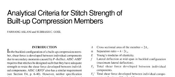
Using the channels a stiffener raises another possible source of horizontal bolt shear if your intent is to use the channels as a built-up, weak axis composite member. Analytically this exercise is a bit complex and I had to purchase the paper below to do it myself back in the day. I'd favor two, simpler approaches if they work:
1) do the welding and know that it's overkill for this purpose.
2) don't use the channels compositely for the stiffening function.
Note that, for composite weak axis behavior, I probably would want either welding or slip critical bolting. And the welding is probably going to be the cheaper of the two.

Ganesh Persaud
Structural
You should check the slenderness, although this slenderness limit is not essential to the structural integrity; it merely assures a degree of stiffness such that undesirable lateral movement (“slapping” or vibration) will be unlikely. Out-of-straightness within reasonable
tolerances does not affect the strength of tension members. Applied tension tends to reduce, whereas compression tends to amplify, out-of-straightness.
Because of strain hardening, being loaded in horizontal shear can resist without rupture a force greater than the product of its gross area and its specified minimum yield stress. However, excessive elongation of the member due to uncontrolled yielding of its gross area not only marks the limit of its usefulness but can precipitate the failure of the structural system. On the other hand, depending upon the reduction of area and other mechanical properties of the steel, the member can fail by rupture of the net area at a load smaller than required to yield the gross area. Hence, general yielding of the gross area and rupture of the net area both constitute limit states.
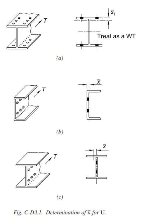
Have a read at AISC Manual Section D.4 commentary.

The reason for having weld and keeping the bolts is simply I don't feel comfortable with this type of built-ups, when stressed to large deformation, the plate and the web of the channels won't behave nicely, and I image the webs tend to bulge outward, thus a bolt or two would help. Again, the bolt shall be designed for the tributary load, assuming the middle taking the full load and distributes to the channels through the bolt. Quite a conservative design, but I think this is the price to pay for not using standard shapes, since the true behaviors of this built-up are everybody's guess.
retired13 said:...and I image the webs tend to bulge outward, thus a bolt or two would help.
Ah, buckling prevention... I see what you mean. Kind of like the plug welds on moment frame connection web doublers.
- Status
- Not open for further replies.
Similar threads
- Replies
- 2
- Views
- 11K
- Replies
- 15
- Views
- 6K
- Replies
- 10
- Views
- 13K
- Question
- Replies
- 6
- Views
- 7K
- Locked
- Question
- Replies
- 5
- Views
- 3K


