Continue to Site

Eng-Tips is the largest engineering community on the Internet

Intelligent Work Forums for Engineering Professionals

  • Congratulations waross on being selected by the Eng-Tips community for having the most helpful posts in the forums last week. Way to Go!

Offset surfaces as Datum 1

Status
Not open for further replies.

dthom0425

Mechanical
Dec 6, 2018
46
Hi all,

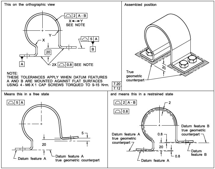
I have a machined part that has offset surfaces...somewhat similar to what you'd see in Y14.5-2009 Fig 4-22.

From a functional standpoint, my part mounts on offset surfaces...just like what Y14.5 shows. I attached a picture from Y14.5-2009 for the offset part.

So my question is regarding inspection of the coplanarity (profile) between the two surfaces.

How would you inspect this using a CMM? Would you need to make gage block that mimics the offset and lay the actual part on top of that? If so, how does the probe verify the profile if the probe doesn't have access?

Sorry - I'm not an inspection master.

Thanks for any help
 
 https://files.engineering.com/getfile.aspx?folder=4509a823-ad0a-41a4-9ac3-66582a5ec9cf&file=offset.JPG
Replies continue below

Recommended for you

dthom0425,

Evaluating a feature for conformance and utilizing said feature as a datum feature for reference in other controls are two separate concepts*. Take the fig 4-22. The pair of offset surfaces must be measured to ensure they conform to the 2X 0.8 profile tolerance. Then they are utilized as datum features to constrain the translational and rotational DOFs of the tolerance zone specified by 3.0 profile to |A-B|.

Hard gauges may be utilized as datum feature simulators (stacked gauge blocks combined with a surface plate as you suggested or something custom fabricated) or if all features can be accessed in a single setup these datum features may be simulated virtually by fitting planes in your CMM software. See ( for some notes on the latter case.

*With the exception of self-referencing datum features. I won't go into that as it doesn't answer your question.
 
I will recommend to see the same picture of 2018 version, it gives more detailed interpretation on the tolerance zone.

2020-04-30_123616_ivcywx.jpg


Season
 
Thanks for the replies.

So I guess I'm still just wondering how you would ensure the two offset surfaces are coplanar to .8. There's no datum feature referenced in the feature control block so would the profile act more like flatness?

If that's the case, do you set this part up on some offset jackscrews and run a dial indicator underneath?

I'm not quite understanding how a CMM could create theoretical datum feature simulators. What does that look like on the actual machine?
 
dthom0425 said:
so would the profile act more like flatness?
Yes -- think of it exactly like flatness.
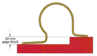
Simply create a step of 20 mm (a gage block) to hold up the right-hand leg of that clamp. That sort of takes away the offset, and the theory becomes the same as flatness.

John-Paul Belanger
Certified Sr. GD&T Professional
Geometric Learning Systems
 
I will use a 20mm physical gage block to create the step, this will be easier and practical no matter you are checking it by a dial indicator or CMM.

2020-05-02_204117_c2sfyp.jpg


Season
 
So when it's on the gage block - how does the probe sweep the two offset surfaces for coplanarity? Isn't the gage block essentially blocking off any use of an indicator/probe?
 
Set the part in a vise with the faces up. Pile on the gage blocks and adjust the item in the vise until sweeping the large one gives zero offset, just like checking for flatness would be done. Then remove the blocks. Sweeping each of the faces gives a reading that tells what the variation is, knowing that the highest point(s) of each were at the desired basic offset; to pass, the variation in reading for each face is less than or equal to the tolerance.

To be absolutely sure, use an unequally disposed profile tolerance such that all the tolerance is on one side of the gage blocks, just like the part would mate on installation.
 
dthom0425

Hi ,

Is your component as unstable as the suggested illustrations ?

Also what is the material of your part ?

Regarding checking the two offset planes.

If the job is not large batch work .

Have you ever tried using glue on your part to stick to an aluminium surface or fixture . If this part was sitting on its front or back ( not the offset faces )

If you simply glue around the component , this puts no stress or force onto the components itself. You can then go in with the probe and easily check this full part.

This wont tell you much in terms of how the part exactly will sit on the mating part , however it will tell you a lot of about the discrepancies in your part .

ALL depending on your tolerances, complexity and part rigidity . This would be virtual Datum simulators created by CMM software rather than using physical Datum Simulators. Accuracy would depend on the sophistication of the software.

Also regarding two planes that have to be as close to perfect to one another as possible . I would be interested to see your machining programming methods to ensure this.


Thanks

Ross


dthom0425

The picture shows how we set up the datum simulator according to the drawing, what you said is ture you can't check the surface profile when the part is sitting on the datum simulator, but you can try:

1. For a guick check, you may use a feeler gage(thickness gage) to see the gap variations on the datum simulator(you can check both side of the clamp legs).
2. Take two gage blocks of same height(say 10 mm), and take another two gage blocks with same height(say 30 mm), the difference on height will create a datum simulator with 20 mm step, place the part on it and you can indicate underneath now.

Season
 
Seasonlee

How do you feel about checking the part using a CMM . A CMM can be dangerous if the part has poor form etc. If this part in question was checked sitting on the flat side faces .
If you take an array of points on both the flat Datum planes. The only concern you would have that is it would be difficult to check how it would sit against a mating part.

It would tell you however pretty accurately depending on the accuracy and type of CMM software .

You find out the flatness of each plane , parallelism between the two planes to a certain degree. If for example the CMM uses the least squared method for planes. it will tell you a very decent estimate of size between the planes. This would be depending on how good the part as been manufactured.

If you are starting to see error in any of these then you could investigate to more on where on why the error is happening . Then go ahead and see how it fits against a mating part of inspection fixture etc.

I like you idea of using shims ( feeler gauge ) etc . However i always use manual checks to back up my readings. This is only because our CMM is insanely accurate.

an insight into your philosophy of inspection would be good.

For example a component might get checked differently during a machine operational 1st off rather than a final QC check.


Ross

 
Ross

I am not a fancy of CMM inspection, but I do realize CMM is a powerful measuring device. It seems CMM is your sole measuring tool from your recent posts, I would recommend to think about the open set up method for some simple part inspection, and the functional gage for a mass production part.

Sometimes the verification of a MMB modifier part can be easily checked with the use of a functional gage but its will be more challenging by using a CMM. And sometimes for the verification of RMB modifier parts can be easily checked with the use of CMM, but it will be really a hard time by using a functional gage.

As for the open set up method, its really a common way used in most QA/QC lab.

We can't always kill a fly with a gun.

Season
 
dthom0425,

You mentioned that your application is "similar to Y14.5-2009 Fig 4-22."
Y14.5-2009 Fig 4-22 has a note that specifies exactly how the tolerances apply (mounted and torqued on a true geometric counterpart).
This note will certainly help with inspection and the "feeler gauge [or pin-gauge]" method proposed by SeasonLee should work for that.

Does your application have a similar note that provide similar guidance?

Cheers, hatsegal
"Think first"
 
dthom0425,

Is your difficulty in getting the CMM software to measure a profile tolerance with no datum features, or in measuring surfaces that have to be clamped down onto a block because of a restraint requirement? You mentioned that this is a machined part - does this mean that it is essentially a rigid part?

Evan Janeshewski

Axymetrix Quality Engineering Inc.
 
Status
Not open for further replies.

Part and Inventory Search

Sponsor