Continue to Site

Eng-Tips is the largest engineering community on the Internet

Intelligent Work Forums for Engineering Professionals

  • Congratulations waross on being selected by the Eng-Tips community for having the most helpful posts in the forums last week. Way to Go!

Arc as a datum?

Status
Not open for further replies.

dthom0425

Mechanical
Dec 6, 2018
47
Hi all,

I attached a picture of a similar part to what I'm working with.

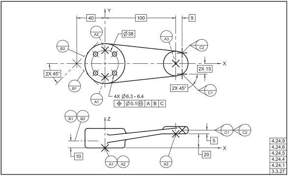
Datum feature A is the rear flat face. Datum feature C is the width of the part (centerplane).

Datum feature B is giving me some heartburn with how it's shown. That particular feature is a cylindrical surface. Is it correct with how it's shown? There are other features on this part that I have removed and they are basic dims coming off of the proposed datum feature B.

Feature control frame for the features not shown are all A|B|C

Thanks in advance
 
 https://files.engineering.com/getfile.aspx?folder=ba524d73-3efe-4b65-b787-91c63057c8d8&file=image001.png
Replies continue below

Recommended for you

Maybe you can use B as a datum target point or datum target line. Just saying.
 
Agree with greenimi that datum feature B can better be defined by a datum target.
Without knowing the function, I dare to guess that probably it is better to change the datum precedence order to make the width that is currently datum feature C the secondary after A. The arc-shaped feature should probably only constrain one translational DOF and be tertiary.
 
Here is one way to use arc as a datum:

Capture1_lgfdcw.png


Here is another:

Capture2_jgogxc.png


Simply pointing to the arc and saying "this is a datum" doesn't work.

"For every expert there is an equal and opposite expert"
Arthur C. Clarke Profiles of the future
 
Thanks for the quick responses...agree with all of you.

Just going to pull on this thread a little bit more...so if datum feature B were to stay as it is shown in the picture and the FCF changes to A|C|B.

Datum feature A - locks 3, Datum feature C locks 2, Datum feature B locks 1 and would theoretically just be line contact on whatever hard gage is used. As a secondary datum feature though, datum B, as shown, would generally be confusing and not truly lock the appropriate DOF. Agree?

I do like the profile surface method shown above - thanks for that.
 
dthom0425,

Can you swap datum features[ ]B and[ ]C? The arc makes a perfectly good tertiary datum.

--
JHG
 
dthom0425 said:
Datum feature A - locks 3, Datum feature C locks 2, Datum feature B locks 1 and would theoretically just be line contact on whatever hard gage is used. As a secondary datum feature though, datum B, as shown, would generally be confusing and not truly lock the appropriate DOF. Agree?

Exactly.

dthom0425 said:
I do like the profile surface method shown above - thanks for that.

That method will require an arc-shaped datum feature simulator. Think about how you want that thing fixtured/inspected. If it is sufficient to make line contact with a planar fixture component, specify a datum target line.
 
While I agree datum targets may be a good option, I'm not sure that specifying a datum target line with a cylindrical feature by default implies the datum target simulator is planar even if thats what you desire. A note would make that explicit. Alternately, you could utilize datum target line(s) that are perpendicular to the axis of the arc like CH's second figure.
 
The usual application of datum target line is making line contact with a pin, which may be a good option too. What I have in mind is a pin normal to datum feature simulator A (the primary) and centered on what is now C (and should be the secondary). The datum target line will be specified on the drawing on the extremity of the arc and represented like a point on the left-hand view where the B extension line is currently tangent to. In this specific case, it will probably not matter if a planar or cylindrical datum feature simulator is used to simulate the datum target line, because the type of contact will be line contact anyway.
 
It will of course be line contact whether a planar or cylindrical datum target simulator is used. A pin parallel to the arc axis will not capture the most extreme point on a real part - but it may be close enough for OP's purposes.
 
As long as it only has to constrain translation parallel to datum plane C, it will suffice.

Of course, we can't be 100% certain that this is the best scheme without knowing how the part functions, but it surely makes more sense than what is currently shown.
 

dthom0425,

The short answer is "any (mathematically defined) feature can be a datum feature". But it is also important how to select the datum features, and the order thereof. Something tells me that your DRF may not be right (not saying it is not). Of course, it is hard to know your design intent without seeing the mating part(s). Would you be able to sketch the mating part(s)?
 
Status
Not open for further replies.

Part and Inventory Search

Sponsor