Continue to Site

Eng-Tips is the largest engineering community on the Internet

Intelligent Work Forums for Engineering Professionals

  • Congratulations KootK on being selected by the Eng-Tips community for having the most helpful posts in the forums last week. Way to Go!

Longitudinal Shear Flow on Elastic Stress Distribution 3

Status
Not open for further replies.

FMPJ

Structural
Aug 10, 2020
11
pic.jpg_zvmyf9.jpg


Hi Folks,

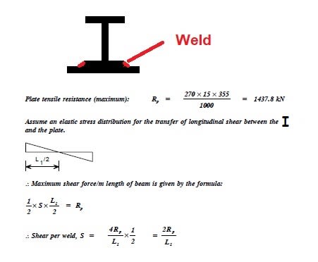
Anyone could please explain the principle shown on above screenshot.
I'd like to understand the relationship between the maximum longitudinal shear and maximum plate tensile resistance when assumed elastic distribution stress.
Thanks for your help.

Best Regards,
JPMF
 
Replies continue below

Recommended for you

Thanks for your response Captain.
The doubt still remains because on the web-page provided by yourself the longitudinal shear appears as shown on screenshot below. And on the initial screenshot (original question) the equation is considering vertical shear equalised to maximum normal force (plate tensile resistance) and I don't really understand why the longitudinal shear is reached out using the normal force (plate tensile resistance) because on screenshot below there is no reference to any normal force.
Thanks.

pic1_ahnbe4.jpg
 
OP said:
...because on screenshot below there is no reference to any normal force.

There is, it's just indirect. [V] is the rate of change of your moment diagram and, therefore, also the rate of change of the normal force in your connected parts. "Bending moment" is really just a distribution of normal force in your cross section. Additionally, it's important to recognize that moment and shear within a member constitute a complimentary set of internal actions. As a result, most discussions of one of those actions implies certain things about the other.
 
Thanks for your response Kooth.

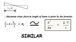
Following your answer we can say both equations are similar, is it correct?
pic2_mfsgsl.jpg
 
I would expect so but it's difficult to say for sure without working through the derivations of the two equations. Different parts of the world seem to favor different presentations of this concept and, often times, use different nomenclature. The equation on the left gives the impression of averaging the weld capacity over the beam halves which I don't agree with. But, like I said, it's hard to tell without seeing the derivation.
 
For pure tension, I will design the weld for the uniform stress flow, f[sub]w[/sub] = T/2A (in unit k/in/in, 2 is for 2 sides), for stress compatibility.
 
JPMF said:
I'd like to understand the relationship between the maximum longitudinal shear and maximum plate tensile resistance when assumed elastic distribution stress.
Thanks for your help.

Actually, it is not quite correct as stated. It is only true if the maximum axial force in the plate is equal to the maximum axial plate resistance.

Let's call the axial force in the plate F when supporting a uniform load w.

F = A*f where A is area of the plate and f is the average fibre stress in the plate under uniform load w. Fibre stress can be calculated using the equation f = M*y/I where y is distance from centroid to middle of plate.

The weld has length L/2 to transfer force F into the plate. The average shear is 2F/L. For uniform load, shear varies linearly from a maximum at the end to zero at midspan, so the maximum longitudinal shear stress is twice the average, or 4F/L which occurs at the support and is the same as your formula except F is used instead of R.


BA
 
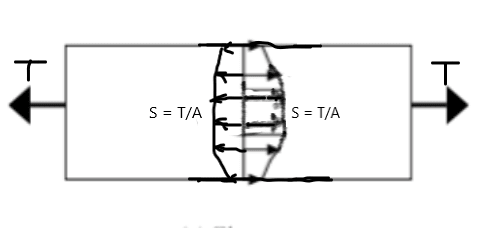
I don't think shear diagram representing the situation that a member subjects to pure tension/compression. See graph below. The stress diagram will be similar without the hole.

image_to8kei.png
 
retired13 said:
I don't think shear diagram representing the situation that a member subjects to pure tension/compression. See graph below. The stress diagram will be similar without the hole.

It may not be clear from the first post, but the beam in question is a simple span beam with a plate added on the bottom as reinforcement. Stress at mid-point of the plate is proportional to the moment M = wLx/2 - wx[sup]2[/sup]/2, which means that the tensile force in the plate varies from 0 at the support to a maximum at midspan.

dM/dx = wL/2 - wx is the rate of change of M, which is also the expression for shear at any point x from the support. The fibre stress at any point x, can be determined using the usual expression, namely f[sub]b[/sub] = M[sub]x[/sub]y/I. The total force in the plate at any point x is F[sub]x[/sub] = f[sub]b[/sub][sub][x][/sub]*A where A is the area of the plate. As y and I are constant, the tensile force in the plate would plot as a parabola, just as the simple span moment does.

The longitudinal shear per unit length in the welds varies linearly from support to midspan, similar to the shear diagram. The average is F[sub]max[/sub]/(L/2) = 2F[sub]max[/sub]/L. The maximum longitudinal shear in the welds is 4F[sub]max[/sub]/L at the support varying linearly to 0 at midspan.

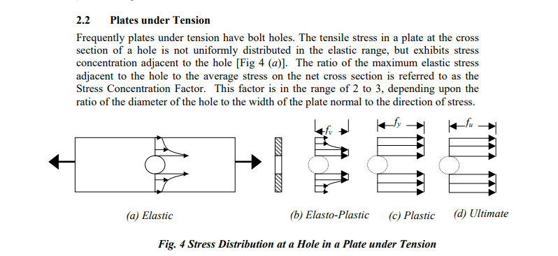
Stresses around holes in a plate, while interesting, has nothing to do with the OP's question.

BA
 
JPMF:
Try thinking of the shear flow or that welding this way…, The stress or strain in the cover pl. is greater than the stress or the strain in the rest of the member or immediately above the point of interest in your bot. flg. cover pl. The shear flow is what binds these planes together, limits their movement w.r.t. each other. That weld (those two welds) must bind the two together, prevent relative elongation btwn. immediately adjacent planes, and account for that relative shear difference, so they act as an integral member. Take a look at any good Strength of Materials or Theory of Elasticity text book for how to size these welds and calc. the shear flow. Also, they should explain the shear or the shear stress magnitude at any length and depth location (a point) in the beam are equal, and that the vert. shear and horiz. shear magnitude are the same at a given point in the beam.
 
Thanks for your response BAretire.

I don't understand when you say,

" The average is Fmax/(L/2) = 2Fmax/L. The maximum longitudinal shear in the welds is 4Fmax/L at the support varying linearly to 0 at midspan."

Any other way to explain this please?

Thanks for your help.
 
IMO, the weld design example is incorrect. What I want to point out is that, for part of a built-up member subject to tension, or compression, the stress flow in no where looks like shear diagram, for which stress is maximum at ends, and equal to zero at the mid span. Instead, the stress flow is uniform throughout the plate length. However, the result is quite conservative, as the total weld strength equal to 4 times of the tension, T, or Ry in the example.

 
Stress in member subjects to pure tension.

t_yssscb.png
 
JPMF said:
I don't understand when you say,

" The average is Fmax/(L/2) = 2Fmax/L. The maximum longitudinal shear in the welds is 4Fmax/L at the support varying linearly to 0 at midspan."

Any other way to explain this please?

I'll try, because I believe it is an important concept to grasp.

F[sub]max[/sub] occurs at midspan because M[sub]max[/sub] occurs at midspan (assuming uniform load on a simple span). M follows a parabolic curve. So does F because F = M*k where k is a constant.

How does Fmax get into the plate? It must be by longitudinal shear in the weld between support and midspan. Suppose (incorrectly) that weld shear is constant from end to midspan, say c (#/" or N/mm). Then c*L/2 = F[sub]max[/sub] or c = 2*F[sub]max[/sub]/L. That means c would be the average shear per unit length.

At x=L/4, the weld has developed only c*L/4 which is only F[sub]max[/sub]/2. That's not enough because F in the plate at x = L/4 is F[sub]max[/sub]*3/4 (ordinate of parabola). The weld needs to develop more shear near the support and less near midspan.

Near the support, moment is growing rapidly as x increases. At midspan, the curve is level which means moment is not changing with change in x. If moment is not changing, there is no need for a weld.

I hope that helps, but we can look at a different loading condition if you wish. What we have been talking about to date is uniform load on a simple span.

Please let me know if the above is clear.

BA
 
retired13,

We are talking about completely different things. You are talking about uniform tension in a plate where the weld is carrying the full tension, a butt weld.

This post is talking about a plate whose edges are welded to a beam under uniform load. The magnitude of tension in the plate varies, similar to the moment, as a parabola.

BA
 
As another example, consider a concentrated load P, at midspan. The moment is P*x between support and midspan, which means that the force in the plate varies linearly in the same range.

M[sub]max[/sub] = PL/4 and f[sub]b[/sub] at midspan = My/I or (PL/4)*y/I

For this condition, the longitudinal shear in the welds is constant, i.e. c = 2F[sub]max[/sub]/L


BA
 
BA,

I think I am confused on the use of shear distribution analogy for the maximum tensile resistance. Where is this tension applied? Can yo elaborate?
image_lgvuxz.png
 
retired13,

The plate tensile resistance would be b*t*Fy where b is the width, t the thickness and Fy the yield stress.
In the example, the plate appears to be 270 x 15 mm and the yield stress is 355 MPa.
Its tensile resistance is 270 x 15 x 355 = 1,437,750N or 1,437.8kN.

The screenshot does not explicitly say, but the intent is that the plate is welded to a steel beam on each edge in such manner as to develop the full resistance of the plate when a uniform load is applied to the built up beam.

retired13 said:
Where is this tension applied?

Tension is applied from each end of the beam to midspan. It is applied by the weld over the full span as a result of a uniform load carried by the beam and plate as a built up section.

The screenshot indicates the maximum value of longitudinal shear 'S' (which would have units of N/mm or kN/m) in the weld to develop the full strength of plate, assuming uniform load on a simple span.

BA
 
BA,

Well explained, I understand fully, but I failed to agree on this approach. For uniformly loaded beam, we know where shear failure occurs, at the maximum on the shear diagram - the ends. Now for OP's example using shear analogy, the tensile force varies from maximum at the ends, to zero in the mid-span. It indicates, same as shear, the failure will be at the ends, which is not true. Maybe I am still missing something then.
 
Status
Not open for further replies.

Part and Inventory Search

Sponsor