Eng-Tips is the largest engineering community on the Internet

Intelligent Work Forums for Engineering Professionals

  • Congratulations waross on being selected by the Tek-Tips community for having the most helpful posts in the forums last week. Way to Go!

Beam in Class 3 compression and 2 bending 8

Status
Not open for further replies.

HanStrulo

Civil/Environmental
Apr 16, 2021
117
CA
Hi everyone.

To my Canadian friends out there, I am new to designing using the CISC and i have a weird question.
I am designing a beam in combined bending and compression. the beam is class 2 in bending and class 3 in compression.

My head has no idea how to reconcile these two classes. Do you take the worst one? are they independent from each other? What is going on?

for a bit of a background, I want to design a beam and reuse it. the beam is W610x155 so i am using the elastic section modulus to determine the bending capacity.

Thank you
 
Replies continue below

Recommended for you

I assume what you mean is you are designing a beam-column. For these members you interpolate between column and beam class criteria.

EDIT - In general it should be said that if there is disagreement between classes the more slender class shall govern. For example, a beam in pure flexure with a Class 1 flange but Class 2 web should be considered Class 2.

beamcols_nzyokx.png
 
Thanks for the visual aid.

I am ok with a flange being one class and the web another. As you said, i just take the higher class.

The issue is that i purposefully chose to design the beam column in class 3 without even checking the limitations because i want it to be in elastic zone for reusing. But for the compression, i just followed the code and found out it was class 2.

Do you know what happens when you decide to design in the elastic zone for bending?

Another note is that the beam is horizontal, it just has some axial forces on it from the supports.
 
There must be some dialect issue between us as I am still a little unclear about what path you are trying to take. The table I gave above is what determines the section class and from there you compute the capacity based on combined stress equations.

Here are the tables from S16. As above, your class is determined by the more slender check (either flange or web). The web check in the case of a beam column involves a linear interpolation between straight axial and pure bending.

S16_rtbtcj.png


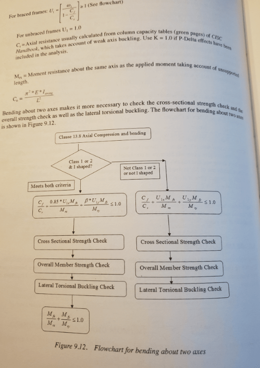
Picture below is your design procedure for combined axial / flexural stresses depending on section class. If you performed calculations based on a more slender section (i.e. designed based on class 3 but actually have a class 2 section) then you can be sure that the design equations for less slender sections would also be satisfied (the other way around quite obviously not). There is nothing else to do in that case as you've just used a less economical member to meet the ULS demand.

You'll need to be more specific if there is something else you are trying to get at.

BeamColumns_pnh6wa.png


EDIT - Maybe you are trying to say you don't want the beam to plastically deform because you want to reuse it? Yeah in that case just design it such that it never reaches plasticity based on the loads (see S16 CL 13.5.1/b) and you're fine. You need to take care to think about non design load damage though (i.e. dropping from height, dudes banging it with the crane, and other things that could induce local issues outside of straight design loads)
 
and the nice thing is, it will behave elastically after you bent it until you reach the load it was subjected to...

Rather than think climate change and the corona virus as science, think of it as the wrath of God. Feel any better?

-Dik
 
@Enable

Sorry for the confusion.

Maybe i can phrase it better. When you design a beam column for combined axial and bending, do you say " beam x is in class 2 for axial and bending" or "beam x is in class 2 for axial and class 3 for bending"?

Also, I did not understand what"a linear interpolation between axial and pure bending" means?

Sorry, I am a newbie with CISC.

Thanks alot
 
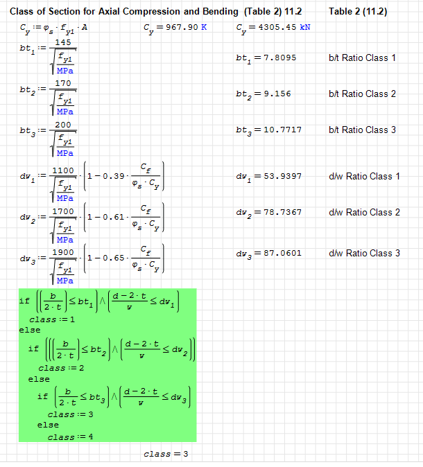
I've never mixed the two... if class 2 and class 3... to me, it's class 3, for everything... The class is a measure of the robustness of the section with class 1 being less likely to suffer from premature local buckling... I'll print part of an SMath program that shows the distinction.

Enable: Is there more to the flow chart you partially printed?

image_grxfxo.png


Rather than think climate change and the corona virus as science, think of it as the wrath of God. Feel any better?

-Dik
 
If you have used the section modulus S, instead of the plastic section modulus Z, for determining the moment capacity of the beam to use in the unity checks, then I believe you're being conservative. Even though you could theoretically use the plastic capacity for a class 2 section, I understand that you'd prefer to stay in the elastic zone. Therefore your proposal would be conservative.

I don't have my design handbook in front of me, but I believe for sections subject to bending and compression it boots you to the bending only section for moment capacity to use, as long as you follow the class 3 method even though you have a class 2 beam then you'd be fine.
 
HanStrulo: I think you might be mixing up a bit of terminology. So lets take a step back to ask ourselves what exactly these class identification criteria are used for. They are intended to address issues relating to how member capacity can be limited by local buckling (rather than global buckling) in certain circumstances. Unfortunately the presence of local bucking means we need to check to see if it governs the design, which would otherwise be a lot of work. However, by assigning a cap to the global capacity based on slenderness, these local buckling checks are implicitly already done for us! The criteria essentially make it so that we, as designers, don't have to worry about local buckling checks or knowing when they will govern our designs.

As you no doubt know, buckling is a phenomenon that only appears in compression members. So when you speak of class identification it is not of compression versus bending, rather it is of pure axial compression versus flexure induced compression (Tables 1 and 2 respectively).

If you take a look at Table 1 from S16 above you'll see that axially loaded compression members don't even really have classes. They have absolute limits. And unless you fancy an adventure, you always just stay under the limits. So really there is no such thing as "class 2 for axial" as you can see. There is only under the limits or not for pure axial compression!

If you look at Table 2 you'll see there are ranges and classes for various ratios for flange and web dimensions for members in flexure. For W-sections the flange limit / class is irrespective of axial loading. Nothing to do with it! As far as a flange check is concerned a beam is a beam is a beam. The web check is another matter. You'll note the presence of axial load modifiers contained within the web class check (1 - 0.39Cf/Phi*Cy) and these are constructed such that they are interpolated between full flexure and full axial.

Here is what I mean:

Axial Only Members
h/t <= 670 / sqrt(Fy)

Flexure Only Members (class 1)
h/w <= 1100 / sqrt(Fy)

Combined Flexure and Axial (class 1)
h/w <= 1100 / sqrt(Fy) * (1 - 0.39Cf/Phi*Cy)

Lets investigate that combined check. What happens if the factored compression force, Cf, is at max capacity for the member?

(1 - 0.39Cf/Phi*Cy) clearly equals 0.61 which if we put back into the combined equation we get

h/w <= 1100 / sqrt(Fy) * 0.61 = 671 / sqrt (Fy)

That's the exact same as the Axial only member (after rounding)!

What if the compression force is 0? Well the multiplier equals just 1 and we get

h/w <= 1100 / sqrt(Fy) * (1 - 0) = 1100 / sqrt(Fy)

The criteria for flexure only!

That's what I mean by linear interpolation between full axial and full flexure. It's already taken into account in that equation set for webs in Table 2.

Mixed flanges and web classes
As dik noted, the most slender class governs the design for everything. So if a web is class 1 but the flange is class 2, your member is class 2 for all design purposes. This has to be the way or local buckling will occur before you reach your design capacity.

Beam Columns
The only checks you need to do for beam columns (for local buckling purposes) is the flange check in Table 2 and the web check in table 2. No different than for pure flexure members. Of course, as noted the more slender class governs the design. Hopefully it is clear now that there is no separate check for class of a beam column member considering only axial compression. It is inherent in this check from Table 2!

In the above example (class 1 web, class 2 flange, meets requirements of Table 1 for axial compressive members) we would say this member is class 2. Full-stop!

dik: Not cut-off per se but it does continue to discuss what happens when bending occurs in both axis directions

SecondFlow_k1v1yi.png


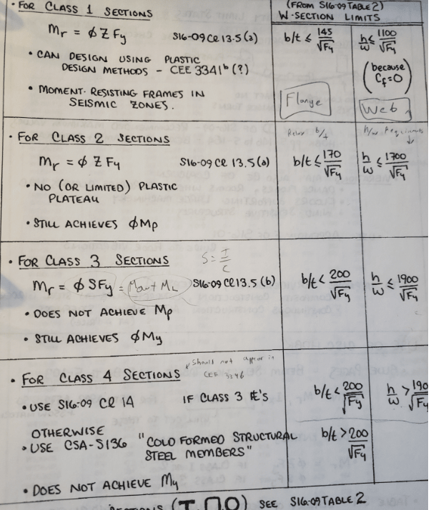
jayrod: You are correct. Moment capacity is determined by pure flexure equations up in sec 13.5 like the following

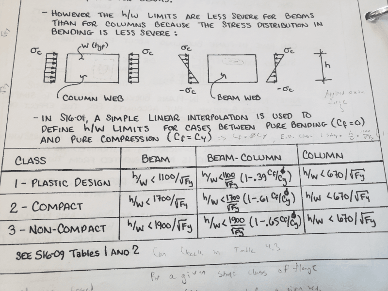
Class_Properties_ffiwdh.png
 
@ Enable

Thank you so much for the explanation. I understand much better now. (Man was I confused!!!).

I also understand now that to determine the capacity in bending for a beam-column, you don't really have to go calculate the applied Cf and plug it to the equation, you can just assume that the beam-column is in pure bending and use those limiting values to determine the class and use that to get the capacity in bending.

Is my understanding correct?

 
Essentially yes, if you go through clause 13.8 it tells you word for word where you need to get the appropriate Cr and Mr from. If you want the beam to remain plastic from the bending, when you determine the MR use the class 3 requirements instead of the class 2.
 
I'm late to the party, but table 1 is for compression, table 2 is for flexural compression. A beam or column (beam-column to be more correct) in compression and bending is a member in flexural compression, and table 2 applies. A column or brace with pure compression is the only case table 1 applies. You'll never have a member with a different classification in table 1 for compression and table 2 for flexural compression - it's either a column or a beam/beam-column, it can't be both.
 
That's why I posted the SMath code showing Table 2... I have other SMath programs just for compression.

Rather than think climate change and the corona virus as science, think of it as the wrath of God. Feel any better?

-Dik
 
This all makes sense now.

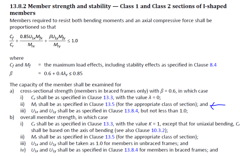
additional question. what does "with the appropriate class of section" mean? the title is already class 2 or class 1.

Capture_iomyzw.png
 
Yes... one using the Elastic Sx (Class 3, 4) and one using the Plastic Zx (Class 1, 2)...

Rather than think climate change and the corona virus as science, think of it as the wrath of God. Feel any better?

-Dik
 
HanStrulo said:
The issue is that i purposefully chose to design the beam column in class 3 without even checking the limitations because i want it to be in elastic zone for reusing. But for the compression, i just followed the code and found out it was class 2.
This paragraph brought me the following question: if you design a beam using a class 1 section, and the design live load happens (reaches Mr calculated with a plastic modulus), will your beam plastify under the load and stay curved?
 
If it's not a class 1 or class 2 section and you use Zx, if the load goes to Mr the beam will fail in flexure... not always bad unless you have a cantilever [lol]... A class other than 1 or 2 may fail locally by buckling before Mr is reached. Just added... even if I don't need stiffeners in beams continuous over columns, I still add them... in the event of an overload, they help maintain the stability of the cross-section.

Rather than think climate change and the corona virus as science, think of it as the wrath of God. Feel any better?

-Dik
 
I agree with you for the addition of stiffeners dik, I also do that.

I understand that a beam not in class 1 or class 2 would fail if you use Zx in your Mr calculation, and the load reaches Mr.

But say you have a beam with a class 1 section, you calculate Mr using Zx. One day, the load reaches Mr. Does that mean that the beam will go over yield (plastify), and stay deformed?
 
Status
Not open for further replies.
Back
Top