Eng-Tips is the largest engineering community on the Internet

Intelligent Work Forums for Engineering Professionals

  • Congratulations waross on being selected by the Tek-Tips community for having the most helpful posts in the forums last week. Way to Go!

Calculating Clamp Force

Status
Not open for further replies.

Mark_555

Mechanical
Aug 2, 2021
3
0
0
GB
Hello All,

I'm new to this forum. Have found it very useful over the years so finally decided to join!

I have a problem to get to the bottom of and would like a hand to ensure I get the correct answer.

We have a construction application (Side-Grip) which is used to drive steel into the ground. I'm trying to establish the clamp force generated.

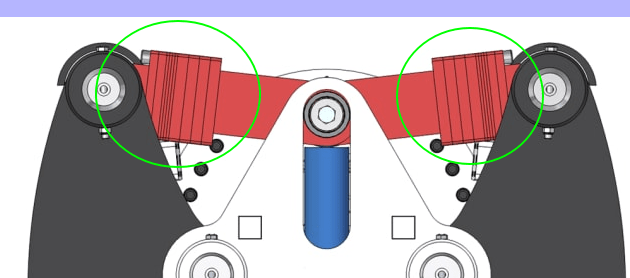
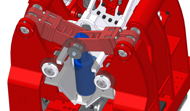
(x2) arms which hinge are driven by a hydraulic cylinder. When the cylinder is extended the arms pivot forming a clamp.

I've tested the clamp force of the cylinder on the application and recorded 64t but would like to make sense of the what's going on as we were expecting closer to 100t. There are some obvious friction point which would reduce the clamp force, but didn't expect it to be so much!

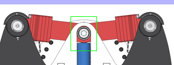
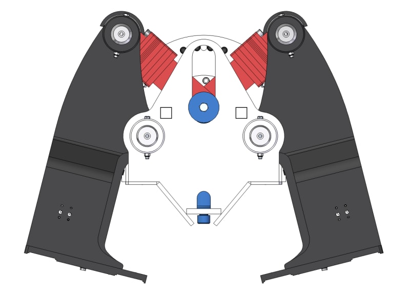
The cylinder (blue) is in the retracted position here:

01_toinr7.jpg


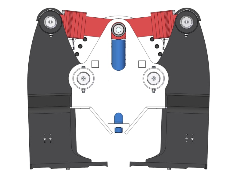
Cylinder extended shown in the image below:

02_jt6zw3.jpg


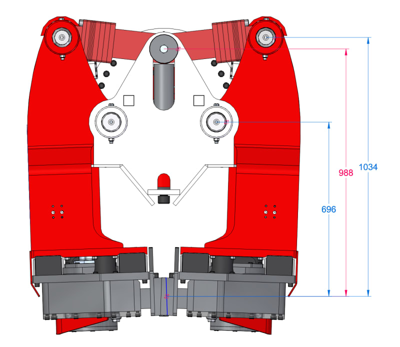
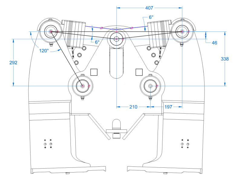
A few dimensions and angles for calculations:

03_peaf2f.jpg


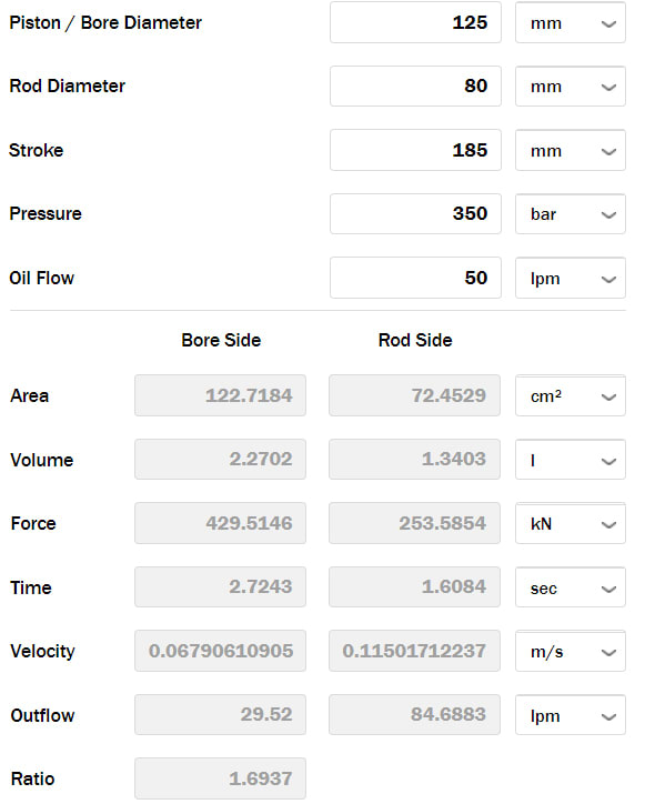
Some additional info on the cylinder (ignore flow)

hhh_ttomvo.jpg


Thanks in advance guys!
 
Replies continue below

Recommended for you

Hi Mark 555

well if you are talking metric tonnes then you don't have sufficient force in the cylinders, you need 490.5kN on the full bore side of each cylinder. Also then the mechanical advantage of the clamp will reduce the clamping force due to the arms being longer than the pivot arm to cylinder. What is the distance between the pivot and the clamping point. looking at the mechanism I would say 64KN was about right.


“Do not worry about your problems with mathematics, I assure you mine are far greater.” Albert Einstein
 
Thanks for getting back to me.

Yes, I'm talking about Metric tonnes. You're quite right regarding the cylinder force. Appreciate it.

Bit of an odd scenario; the company I work for purchased this application for further development. Unfortunately the CAD we received doesn't match the actual item. It appears the clamping part interferes in this image, but this is not the case in reality. The measurements from hinge points to Clamp are shown below:

Untitled-1_hpk9kz.jpg


Thanks again
 
Hi MintJulep The plates inside the arms are to allow adjustment. We can add or remove these depending on the size of what needs to be clamped. Typically clamping steel up to 20mm thick between the jaws, however large tubes need to be handled at times (700mm OD). We realise this significantly alters the clamping force.

I've hidden a few parts for clarity in my previous images. Please refer to the hinge / arm mechanism in the image below:

gh_yfdhen.jpg
 
Hi Mark 555

According to my calculations when the arms driven by the cylinder are at 6 degrees I calculate a clamp force of around 992KN however when you grip various thicknesses of steel that angle of the arms will change and as a result of that so will the clamping force, what sort of thicknesses do you clamp ie max and min?

“Do not worry about your problems with mathematics, I assure you mine are far greater.” Albert Einstein
 
One issue is that the device is adjustable, so how accurate is the 6 degree value? The device is capable of theoretically reaching infinite clamping force.
 
Is the roller bottoming out in the slot? Maybe some oil pressure on the rod end of the cylinder?

As Compositepro said, the linkage gain goes to infinite as the upper links get close to horizontal. Same with sensitivity (Clamp force/Actuator force). If the link loads are getting high then maybe the horizontal bearing loads are getting high. Also everything will deflect more when the load gets real high so maybe the geometry is off a bit.

Is the upper roller side load path stiffer than the actuator side load stiff path? Looks like it would be unless there is slop in the fit to the slot.
 
although from the later pix it looks like the grippers bottom out before the links are horizontal ... the clamps touch with a reasonable angle in the links.

another day in paradise, or is paradise one day closer ?
 
Mark_555:
Your sketches look like an incredibly complex and heavy device for picking up a piece of some sort of piling. It might be helpful if you explained what you are really trying to do, other than win this year’s Rube Goldberg prize. In applying a driving force to the pile member, be that hammering, pushing, vibration, whatever, this force should not be applied through that blue vert. clamping force cylinder. The driving forces/operation should be through a solid load path from the hammer to the pile. It might be easier and more accessible to apply the grip thickness adjusting pls. down at the clamping pad area. Then, all of a sudden (at post 3AUG12, 13:02), you show a whole new level of complexity down at the clamping pad area. Then, finally (at post 3AUG21, 14:35), when you look down into that mechanism, I suspect a machine shop could build a completely new diesel engine, from scratch, in less time and for less cost. Again, tell us what you are really trying to do. No pile driving contractor in his right mind would be interested in, or buy, that thing, it’s just too complicated. There must be an easier, cleaner way, and we should be discussing that, because the statics problem should be pretty straight forward for an engineer.

Real good engineering and good clean design are many times as difficult or more difficult than something that looks so complicated that no mechanic could possibly understand it, or take it apart, or build it. Cleaning the design up, making it easy to build, maintain and operate is part of the art of good design. And yet, many people are deceived. They see the complicated machine and think that must be real engineering, look at how complex it is. And, the cleaner design which does essentially the same thing goes almost unnoticed for its simplicity.
 
Status
Not open for further replies.
Back
Top