Continue to Site

Eng-Tips is the largest engineering community on the Internet

Intelligent Work Forums for Engineering Professionals

  • Congratulations KootK on being selected by the Eng-Tips community for having the most helpful posts in the forums last week. Way to Go!

Interior Wood Shearwall

Status
Not open for further replies.

JeffCastillo

Structural
Apr 10, 2021
8
Hello:

I have called our for an interior shearwall on a commercial shop that will be used to fix cars. It is stick-framed and I needed to call out an interior shearwall for a partition wall that seperates two garages. It is not load bearing or anything, and the only reason I called out for a footing under is for I called it out to be a shearwall. I used the perforated method, as there was a door in the far right of the wall but I still met the aspect ratio, however, the concrete guys did not pour a concrete footing under the 5.5" slab. I can't find anything in the code that requires a footing under a shearwall, but I wanted to see if it is somewhere in the code that I can't find to justify that we do need a footing under shearwalls?

I know we need to have anchorage into the mudplate, where we can use red head concrete anchorage to go into the slab to hold the mudplate down to the floor and there will be STHD14 straps on the ends of the wall, but is a footing required per code?
 
Replies continue below

Recommended for you

Without it, your slab is now part of the lateral force resisting load path. When you apply the reaction forces to the slab, what happens? If it can't resist the loads, then it isn't adequate.
 
Wood shearwalls can be constructed on top of wood beams. The only requirement for the supporting member is that it resist the shearwall forces and provide a load path to the soil.

Don't forget the uplift requirements on the mudsill anchor bolts for perforated walls.
 
1) I'm guessing that this is a nice long wall which plays in your favor.

2) Wall base shear. If you can work out viable anchorage into the slab from the sill plate and deal with that load in the slab, so be it.

3) Wall chord reactions and overturning. This may be tougher to deal with in the slab on grade. However, if the wall runs front to back, you may be able to effectively tie the wall ends into framing that does sit on proper foundations at the exterior and deal with it that way.

I don't love this setup but might be willing to live with it.
 
If your bolts are spaced closely enough, then you could consider a triangular distribution for your overturning forces across 1/2 the length of the shearwall. Some one please correct me if I am wrong.
That should make the numbers work out easier.
 
Thank you everyone!! We called out for Redhead anchor bolts at 24" O.C. for the shearwall and told them they need a minimum of 7" Embedment, as it was treated as a perforated method, we made sure they followed the required methods per NDS and verified uplift with the holdowns.
 
XR - I've seen that done, but I've always been leery of it for tension. It seems like we're asking a lot of the nails and sheathing, and when you consider the variability of panel joint locations it seems like a bad idea to rely on distribution of point loads through the sheathing alone. Unless you have studs and a hold down, I'm not ready to rely on it as a tension connection for overturning. I think under service loads the triangular load is probably closer to the true story of the mechanics of the shear wall and exactly what does what is a little fuzzy. But as you approach the design load, I think discreet load path elements become more important.

Compression on the other hand...I think that's reasonable. Even if you break it out to individual compression loads at your stud spacing, it'll still improve things.
 
phamENG said:
Unless you have studs and a hold down,

I suppose adding a Simpson DTT2Z at each stud could be a cost-effective option
 
XR250 said:
Some one please correct me if I am wrong.

I used to espouse similar practices. Then, someone here at ET produced some research from the University of Washington pertaining to the exact case that I was interested in at the time: a shear wall with a heavy post load in the middle of it. I can no longer find the research paper but the result stuck with me: the wall doesn't really feel the post load with respect to it's shear wall behavior. I've sort of reconciled myself with that as follows:

1) The axial stiffness of the post sort of shields the sheathing from "feeling" the concentrated load under what is primarily a racking deformation mechanism.

2) We tend to always think in terms of things that are flexurally flexible rather than shear flexible. Shear flexible stuff like wood shear walls do this business where everything racks to the side by way of rotation of the individual panels. This, mechanically, is quite different from flexural "flexing".

3) I think that we only need boundary members at the ends of shear walls because, there, there's no other way to achieve equilibrium of those last shear panels. We need the boundary members for overturning too, of course, but that's just a different side of the same coin.

I know, I really wish that I could find that UW paper...

By a similar logic to that above, I'm not convinced that a shear wall feels an intermediate hold down in the way that we'd like it to.

 
Fascinating and it makes sense. Thanks for your insights.
 
KootK said:
3) I think that we only need boundary members at the ends of shear walls because, there, there's no other way to achieve equilibrium of those last shear panels.

Would that not imply that the boundary elements only see a tension force equivalent to what is tributary to the last shear panel and that there is consistent tension across the shear wall at each shear panel? Seems like you would end up with a much smaller chord force and the necessity for tension anchorage along the length of the wall.
 
EZBuilding said:
Would that not imply that the boundary elements only see a tension force equivalent to what is tributary to the last shear panel

I believe if you look at the trib. for the panel multiplied by its large aspect ratio you will find the tension is the same as it would be globally.

KootK said:
We tend to always think in terms of things that are flexurally flexible rather than shear flexible. Shear flexible stuff like wood shear walls do this business where everything racks to the side by way of rotation of the individual panels. This, mechanically, is quite different from flexural "flexing".

But what if we think of it as a stubby cantilevered beam?
 
EZ said:
Seems like you would end up with a much smaller chord force and the necessity for tension anchorage along the length of the wall.

You must be envisioning a different model than I am somehow. I see what I've described as having the usual chord forces and no distributed tension anchorage.

EZ said:
Would that not imply that the boundary elements only see a tension force equivalent to what is tributary to the last shear panel and that there is consistent tension across the shear wall at each shear panel?

I'm not clear on what you mean by "tributary" in this context. I see the chords picking up axial load via the delivery of unit shears coming out of the sheathing in the conventional sense of it.

 
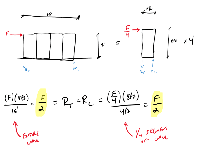
EZBuilding - see the picture below. If we consider a shear wall that's 8' tall and 16' wide, we can assume it's been built with 4 standard sheets of sheathing. Each sheet or segment of the wall has identical in plane stiffness. Therefore, we can consider each as an individual shear wall with its own tension and compression chords. Because each of the 4 segments has equal stiffness, the load will distribute evenly to each one. Due to the shift in the aspect ratio, the chord forces are identical to what they are for the longer wall. When we shove them together, the adjacent tension and compression forces counteract one another and we're just left with the end connections required to satisfy equilibrium.

Wow. That was a fun little exercise. I like the triangular distribution even less than I did before.

Screenshot_2021-12-22_120216_pt4kvk.png


Please pardon my inconsistent use of ft and '
 
XR250 said:
But what if we think of it as a stubby cantilevered beam?

Tough to unpack that without knowing what "stubby" implies in your mind. Rectangular cross section? Flanged cross section? Multi-flanged cross section? Highly shear flexible? For a long, one story shear wall, I'm reluctant to use any term that has the word "beam" in it.

Thinking on this in the shower this morning, I feel that there is at least one, in print, analog for the use of distributed chord forces. If I'm not mistaken, the perforated shear wall method makes use of uniformly distributed uplift resistance.

Something that I've done in the past, and still feel at liberty to do, is to use two adjacent studs as my chords / hold downs where the foundation situation facilitates that. I make sure that the "chord" is no more than 1/5 th the width of the wall, that both studs get boundary nailing, and that the peak shear is adjusted accordingly. This is somewhat similar to the distributed chord approach.

With the distributed chord approach, I think that you'd have to adjust your peak shears to about 150% of the normal value to account for how the distributed chord setup would alter the shear distribution. While that's probably not a big deal for OP's wall, it raises questions in my mind with regard to the truthiness of that distribution. For a long time, I thought that we just assumed shear distribution to be uniform in diaphragm applications because of the convenience of it and the uncertainties involved. I didn't think that was the real distribution. Someplace, I've seen test results on steel roof deck that indicate the assumption of uniform shear stress is actually pretty close to the truth. I feel that supports a "racking" perspective when it comes to these things.


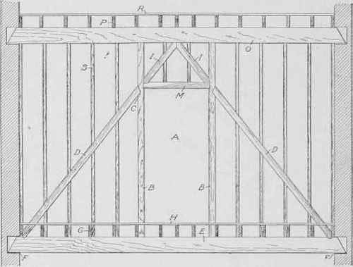
150 years ago the old boys here were doing what you see below. This was often to make a trussed stud wall to span over clear space below. But I’m sure with enough effort on the calcs you could justify something similar to resolve your lateral woes.

Tie the uplifting side into the perpendicular wall to stop it.. well, uplifting.

FBB025B5-7CDD-4A26-8246-5E0CA1A0F7D4_h5wogb.jpg
 
Status
Not open for further replies.

Part and Inventory Search

Sponsor