Eng-Tips is the largest engineering community on the Internet

Intelligent Work Forums for Engineering Professionals

  • Congratulations waross on being selected by the Eng-Tips community for having the most helpful posts in the forums last week. Way to Go!

Composite tolerance on hole pattern of different sized holes.

Status
Not open for further replies.

freerangequark

Mechanical
May 11, 2005
85
US
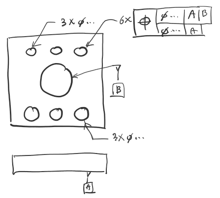
Question: According to Y14.5M, is it permissible to use a composite tolerance to control a hole pattern of different sized holes? If so, how should it be annotated?

I found this thread which says yes.

I also found this tutorial with video which also says yes and references ASME Y14.5M-1994, paragraph 5.11.1.6

In ASME Y14.5M-1994 however, section 5.11 is titled "COAXIALITY CONTROLS".

Does this allow a composite tolerance to control a hole pattern of different sized holes? If so, how should it be annotated?

Can you add any clarity to this matter? The links makes sense to me and it would be rather restricting if a composite tolerance controlled hole pattern could only exist with the same size hole.

Thanks,
Glenn
 
Replies continue below

Recommended for you

Glenn,

There is a figure in ASME Y14.5-2018 with composite position applied to a pattern of 2 different sized holes. It's Figure 10-52. There is a size tolerance for each of the 2 holes, and a 2X in front of the composite position FCF.

Evan Janeshewski

Axymetrix Quality Engineering Inc.
 
To do that one needs to identify which holes are part of the pattern that are grouped. The default is to associate the composite FCF with the size and quantity callout, but that doesn't work with multiple hole sizes. In multiple single line FCFs the relation can be established by implied simultaneous requirements.

For composite cases, one can apply separate composite FCFs to the different size hole callouts and use "SIM REQT" next to the lower segments of the different hole FCF callouts.

2009 and 2018 also allow for using the word "INDICATED", but I don't see a picture showing that use or any description of how it would be used. (Look! Another loose thread. Also, "series," as mentioned in "Series and Patterns" but "series" aren't defined or otherwise mentioned in that context anywhere else either; instead they become "Repetitive Features." And what does it mean to be a "Repetitive Pattern"?)

I don't see an example or justification for the tec-ease method in the 2018 standard, and it's weird to have 3 leaders and also say "3 HOLES," as that is redundant, though they could put "()" around that as a reference item. Most people could figure it out from that information, so it's not uninterpretable, but some cannot handle when there's no exact verbatim example. For this case there's no consideration in the standard where one member of a pattern cannot have a composite tolerance applied to it and so they couldn't use "SIM REQT."

Also not in the standard is to put a letter identifier next to each hole and, for one hole apply a composite FCF with a notation under it "n HOLES MARKED _" and fill in the "n" with the number and the "_" with the notation. Example: "5 HOLES MARKED A" Perhaps this is what "INDICATED" was for and no one wanted to standardize its use.

On a further thought - the way it is used it's not really a pattern of features, it's a pattern of feature locating tolerance zones as the definition requires a pattern is defined based on the application of an FCF. No FCF, no pattern.
 
What you have to focus on when examining 5.11.1.6 and the figure it refers to, is that a position tolerance feature control frame, although mostly placed beneath a size dimension or on the extension of a dimension line, does not always have to be placed that way. Para 3.5 on feature control frame placement also supports this.

From this, the solution becomes clear: indicate the holes you want to control in the pattern by a letter such as "K". Then, apply the composite position feature control frame with a notation INDICATED K, using a leader, to one of these holes, separately of the size dimension.
 
Size of upper three holes and size of lower three holes are different. Composite position FCF is attached to one of the six holes with "6 X". Doesn't this make sense, without a note like "INDICATED"?
2022-10-19_13_11_52-WOOSANG%EC%9D%98_%EC%A0%84%EC%9E%90_%ED%95%84%EA%B8%B0%EC%9E%A5_-_OneNote_for_Windows_10_k5a6qx.png
 
Woosang,
It makes sense, as long as the only hole not included in the pattern is the datum hole. If you have other holes on the part then the question is "which 6?".
 
Status
Not open for further replies.

Part and Inventory Search

Sponsor

Back
Top