Eng-Tips is the largest engineering community on the Internet

Intelligent Work Forums for Engineering Professionals

  • Congratulations waross on being selected by the Eng-Tips community for having the most helpful posts in the forums last week. Way to Go!

Horizontal End Plate Leaning on a Column (Use of stiffeners) 1

Status
Not open for further replies.

oengineer

Structural
Apr 25, 2011
705
US
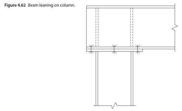
I am looking to obtain some technical info/design data on the use of Horizontal End Plate Leaning on a Column (see image below).

I have seen this pretty much designed as an upside down end plate moment connection, but additional commentary of this type of connection would be nice (especially regarding the use of stiffeners) .
horiz_end_plate_ylec3u.jpg


Comments/suggestions are appreciated.
 
Replies continue below

Recommended for you

Extended end plate with axial load is exactly what it is. I just use the AISC DG4.
 
I think that you need the stiffeners here -- or at least a stiffener -- for beam sidesway / rotational restraint if nothing else.
 
phamENG said:
Extended end plate with axial load is exactly what it is. I just use the AISC DG4.

This is how I design these type of connections. In this type of construction, the beam is braced only at the top flange. However, from some of the technical design documents I have seen, it appears that the stiffeners are used to address a stability issue with this type of connection. I am just seeking technical documents that speak about the use of stiffeners to restrain the motion

KootK said:
I think that you need the stiffeners here -- or at least a stiffener -- for beam sidesway / rotational restraint if nothing else.

This is also what I have come across in my searching for information. Do you happen to have some technical documents that speak to this issue? I have seen some mention of it in AISC Design Guide 24 (which mostly speaks to HSS columns) & a textbook called Design and Analysis of Connections in Steel Structures Fundamentals and Examples by Boracchini, Alfredo.
 
Yes, it's just a bolted end plate moment connection turned the other way. The design for moment would be exactly the same.

For the axial force (i.e. compression) it's pretty much the same way you would do it as well. You assume the compression is split 50/50 between the two flanges. Add that compression force into the compression you get from the moment couple and you check that vs the stiffener requirements. Though, my tendency is to default to including stiffeners (maybe even full depth rather than half depth) on this type of connection. For the same reasons KootK mentioned.
 
How about AISC 360 J10.7 Unframed Ends of Beams and Girders?

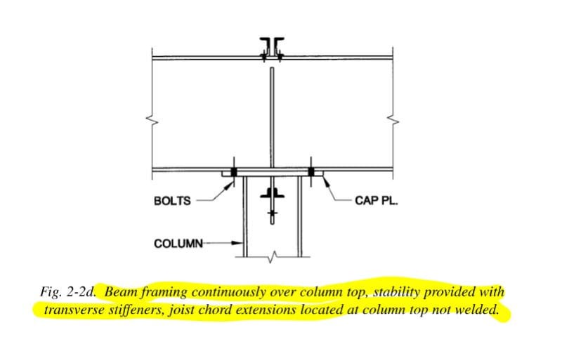
Or Manual Section 2, Beams and Girders Framing Continuously Over Columns (p.2-19 in the 14th edition)?
 
phamENG said:
How about AISC 360 J10.7 Unframed Ends of Beams and Girders?

Is this what you are speaking of:
pic2_j3kaun.jpg


AISC 360 J10.7 looks to be address the stiffeners in regards to stability. Thank you!


phamENG said:
Or Manual Section 2, Beams and Girders Framing Continuously Over Columns (p.2-19 in the 14th edition)?

Is this what you are speaking of:
pic1_ewnihn.jpg


pic3_yflh70.jpg
 
The top one yes, the bottom one almost. There are a few other example details on the following pages that are more applicable to what you have.
 
phamENG said:
The top one yes, the bottom one almost. There are a few other example details on the following pages that are more applicable to what you have.

If you happen to have any images of these details, please feel free to share.
 
I do not, at least not without scanning my manual. Turn the page a few time and you'll see them.
 
Status
Not open for further replies.

Part and Inventory Search

Sponsor

Back
Top