Continue to Site

Eng-Tips is the largest engineering community on the Internet

Intelligent Work Forums for Engineering Professionals

  • Congratulations waross on being selected by the Eng-Tips community for having the most helpful posts in the forums last week. Way to Go!

Negative Pressure in Pipeline

Status
Not open for further replies.

Jack.C

Industrial
Feb 17, 2023
12
Hi all!

I need to solve a small case study and am kind of lost. Hopefully you could give me some valuable inputs or explanations.

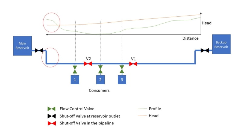
For better illustration of below description, I draw a little sketch (please see below).

Normal Operation:
There is a main reservoir (on a hill feeding 3 reservoirs in the valley. Each reservoir (1, 2 and 3) has a flow control valve (100m3/h). The red valve (V1) is closed during this operation.
Everything works fine like this.

Backup Operation:
Now the main reservoir is out of order and further away, there is a backup reservoir (same geodetical height) which can be used. Therefore, the shut-off valve at the main reservoir is closed and the shut-off valve of the backup reservoir is opened. The red shut-off valves (V1 and V2 are open). During this operation, I can feed all the reservoirs in the valley. However, there will be negative pressure in the pipeline (between the consumer 1 and the main reservoir). I know that in this section there is no flow, but there is a static pressure (if I'm not wrong).

In the sketch I draw the hydraulic head in the system when the back-up reservoir is open, and the main reservoir is closed. The profile of the pipeline is drawn in green color and the hydraulic head during back-up operation in orange. I put a red circle to the section where the head falls below pipeline profile.
Hydraulic_Case_Study_yflcxn.jpg


Could you please tell me if this is physically possible? Can I operate the system like this OR do I need to close the red shut-off valve (V2) that the system works? In this case only consumer 2 and 3 are operable.

Kind regards,
Jack
 
Replies continue below

Recommended for you

I assume by negative pressure, you mean negative gage pressure, not negative absolute pressure.

It will operate as long as there is a downward slope from the main reservoir to the pipe feeding #1.
If there was a high point between the main reservoir and #1, flow would stop (or siphon) there.

Water will always be able to flow down from the reservoir, but don't expect it to go up into the main reservoir. It won't go up higher than the red line.

--Einstein gave the same test to students every year. When asked why he would do something like that, "Because the answers had changed."
 
Hi 1503-44

Thanks for your feedback.
Yes, in this case negative pressure would correspond to negative gage pressure.

So in the above described scenario we don't use the main reservoir for feeding, only the back-up. Main reservoir is not open.
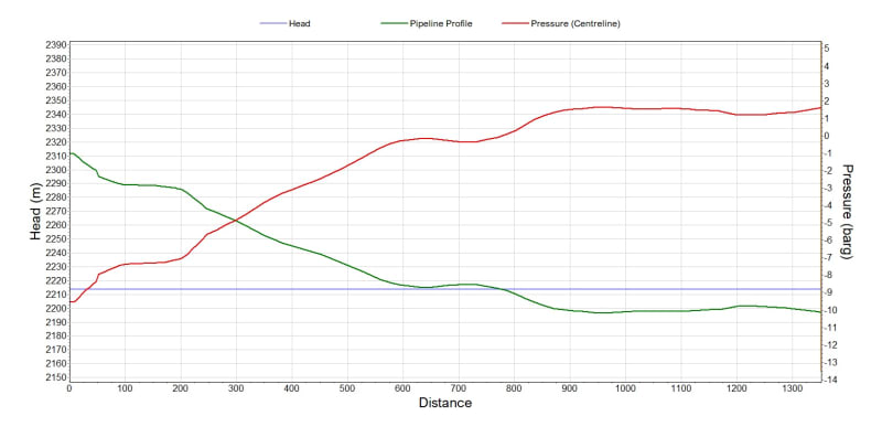
I tried to plot the data (only the section between main reservoir and #1) when the back-up reservoir is used.

green: pipeline profile
red: pressure
blue: head (static as no flow in this section)

So do you think when operating the system like this, there is no risk of cavitation?

Profile_ubwycz.jpg
 
Jack C

I agree as usual with Mr 44.

The system will operate but the section between the main reservoir to consumer 1 will drain down and pull a vacuum in the pipe.

In your diagram in the second post any pressure below -1 barg is physically impossible. What you need to do is draw a horizontal line at -1 barg.

What this then tells you is that 550m of the pipeline from the reservoir has drained down and is now sitting at -1 barg ( full vacuum) or 0 bara.

In reality it will be a little bit higher as the water will start to boil and create vapour, so maybe 0.1 bara depending on the water temperature.

Now this is not a great move as when you open the main reservoir valve again, the incoming water rushes down the pipe at very high velocity, collapses the vacuum and slams into the water already in the pipe. This can lead to very high surge pressures.

So the procedure and timing of how you switch from the standby reservoir back to the main one needs carful thought to very slowly refill the line.

Or just move valve V2 to the left of consumer 1 or as you say close consumer 1 AND V2 before opening valve V1.

I assume valve V1 is the one normally closed and the valve from the reservoir is normally open otherwise the same thing will happen for the standby reservoir?

You were editing as I wrote this so in answer to your last point - There is a very large risk of surge and vacuum collapse. Cavitation is normally inside pumps

Remember - More details = better answers
Also: If you get a response it's polite to respond to it.
 
If main reservoir is off, the pressure will be somewhere between the pressure at take #1 and whatever residual pressure remains from water that was initially drained from reservoir #1 in that now dead leg. If you increase the feed to #1 a lot, you could get a more negative pressure in thatdead leg as some more water will de drawn down from it. Best to design that leg for full vacuum. Same applies to the other side, if you reverse the situation.

Yes, now seeing that 120m difference in head, you will most assuring get a near vacuum (vapour pressure of water) in the dead leg near the main reservoir at one time or another. Depending on the feed rate to #1, it may extend all the way to nearly that point.

If you design the pipe with enough wall thickness to resist full vacuum, you should be OK, but ..
Pressure spikes from long near vacuum pipelines can be pretty high and best to avoid if possible. When you open up reservoir 1 again into a vapor filled line, that water will pick up a lot of speed and when it hits the liquid water somewhere below, could be some impact there. I would want to avoid that pressure spike.

My suggestion would be to install another valve at feed #1 in the line from the main reservoir. That would be a "backpressure control valve". You would set that valve to hold the 110 meter head at that point in the pipe from the main reservoir. So it would hold 11.0 +/- bars there when reservoir 1 valve is closed. To restart flow from reservoir 1, you would open its valve, then slowly reduce the backpressure setting of feed1's backpressure control valve. Eventually, and slowly, reducing that setting to whatever pressure gives you your target flow rate into feed1.

You should consider duplicating that backpressure control valve setting on the other backup reservoir line. I'd put it between valve 1 and feed 3. As Control valves usually have block valves on the reservoir side to allow shutoff for maintenance purposes, valve 1 can stay. I would also add a block valve on the reservoir side of feed1's backpressure valve for the same reason.

Did you get all of that? Need more info or a sketch?

--Einstein gave the same test to students every year. When asked why he would do something like that, "Because the answers had changed."
 
Mr 44,

If the BPV is set at 100m he won't get any flow because the standby reservoir is at the same height as the main reservoir so very little head, especially if consumers 2 and 3 are taking a lot of water....

Move valve V2 or add another valve or close V2 and consumer 1 BEFORE switching to the reserve reservoir are you best options.

And yes, check the pipe for full vacuum. PE pipe doesn't like full vacuum, but steel or cast iron should be ok.

Remember - More details = better answers
Also: If you get a response it's polite to respond to it.
 
As 11.0 bars is rather a high pressure and you have the potential pressure spikes to think about, I'd suggest some transient pressure analysis. That would confirm the probable maximum transient pressure and tell you that you will probably want to have a pressure relief valve or two and probably a tank to put the water outflow from the relief valves in until the transient pressure comes back down to safe levels.

--Einstein gave the same test to students every year. When asked why he would do something like that, "Because the answers had changed."
 
LI, I think high takes at 1, 2 and 3 might drain a lot of the main reservoir line. Don't know the possible flows, but it seems like that could easily happen. In that case the potential vacuum situation might be set up and opening the main reservoir could lead to those pressure spikes. It all depends on how low the feed 1 pressure gets when being feed from the backup reservoir. If it goes lower than 11 bars, the dead leg column height decreases. If its 1 bar, there's a lot of that line empty.

There could be a careful operation plan to work around pressure spikes on restarts, but will it be safe? Will it be easy to coordinate closing one valve or two while opening the other? That's an op question. I'm not there yet. Let's think about options for now.

--Einstein gave the same test to students every year. When asked why he would do something like that, "Because the answers had changed."
 
Your other option is to install a vacuum releif valve / vent just downstream of the main reservoir and let air in.

Issue then is that when you restart you have several hundred metres of air filled pipe and now needs to release the air or let it go through to the outlets and there will be a lot of glugging and surging going on so not ideal either.

However this all depend son whether when you change from the standby to the main reservoir you can turn off the three consumers and let the stand by reservoir refill the line and vent the air and then turn off valve V2 before opening the reservoir valve?

Might be a lot easier to do that, but needs good procedures in place.

Remember - More details = better answers
Also: If you get a response it's polite to respond to it.
 
Jack C - Can you give us the full picture? Where are offtakes 1,2 and 3 on your second graph?

Remember - More details = better answers
Also: If you get a response it's polite to respond to it.
 
Yes. Right. Let's give Jack a chance to have his say now. See where he wants to go with this.

Jack, some flow rates at the feeds (consumers) would be great to know.

--Einstein gave the same test to students every year. When asked why he would do something like that, "Because the answers had changed."
 
This is what is know as "slack flow". Try to google it.

--- Best regards, Morten Andersen
 
Dear all

First of all thank you very much for your explanation - highly appreciated. Now everything makes much more sense to me! Especially what phenomenon could potentially occur.

@MortenA: Maybe I should read a little bit more about "slack flow" in this case to understand more about the phenomenon.
@LittleInch: Actually the system is much bigger and more complex than what I've sketched above. Above description is just simplied. Unfortunately, I cannot post a full picture yet.
@1503-44: At this stage, I'm super happy with your explanation and the approaches you proposed to deal with this scenario. I'm actually about to model a transient analysis, however the software does not accept the initial condition and gives me an error because of that negative gage pressure in the first section.

To be on the safe side, I will definitely add another valve between the main reservoir and #1 to avoid vapour pressure. This valve will then need to be closed in case of backup operation. Or another solution is to close valve V2 which means #1 does not receive any water.
Actually this will then result the same "set-up" wich I normally have when using the main reservoir to feed #1, #2 and #3 with V1 closed.

Regards,
Jack
 
Great. Yeah, most liquid simulators blow up, at least while the solution does not converge at points where pressures drop below vapour pressures. You have to start with a stable scenario, operate as you will until you hit vapor pressure, let the program try to continue as you get hundreds of failure to converge solution messages as you try to increase pressures at those points to higher levels. My program will usually muddle through, but you have to be aware of potential bad data at those points. I can play with vapour bubble collapse and such, but it's not easy, or extremely accurate. It's better to work down as close to vapor pressure as you can get and see what transient pressures are reached in the 100% liquid state and do not actually let it go into the vapor state. Close a fake valve or something. Develop a work around.

If you have slack flow, it's not really a problem if it's stable slack flow. What you want to avoid is collapsing vapor pockets and repressuring them back into liquid successions. If you stay in slack flow, you switch that section of the analysis to gravity flow calculations, usually done separately by hand. Just like an unpressurized flow sewer line, either in flowing full at hydraulic head pressure only or like in an open channel flow regime. Just stay out of the liquid to vapor to liquid transition regime. Then it either operates one way, or the other. Make any transitions well controlled. Fill up the pipe from the other reservoir as much as you can first, before opening up the closed reservoir. Don't jump between extreme head differentials.

--Einstein gave the same test to students every year. When asked why he would do something like that, "Because the answers had changed."
 
Slack flow as its name implies requires flow. /This is a different scenario.

Analysis programs find this sort of stuff difficult to deal with alright, but it can be done.

I don't like slack flow as it has few advantages and many disadvantages. Too much can go wrong and when it does you can break your pipeline. Open channel flow is different.

They had to adjust the TA pipeline doing this because the ground started shaking...

Remember - More details = better answers
Also: If you get a response it's polite to respond to it.
 
You must not operate near the critical flow rate where flow oscillates between sub-critical and super-critical ve.ocity, particular to a given channel shape and its slope. If you can do that, there should be no shaking.

--Einstein gave the same test to students every year. When asked why he would do something like that, "Because the answers had changed."
 
I think this was the point where the slack flow returned to "normal" packed flow but they seemed to run too much of a long slack section so the fluid increased in velocity too much and then ran into a wall of liquid and liquid / gas. They increased the back pressure a bit more and moved the problem further back up the hill apparently.

Anyway, I avoid designing any system I'm involved with to operate in slack flow.

Remember - More details = better answers
Also: If you get a response it's polite to respond to it.
 
The hydraulic jump, where super goes sub.

--Einstein gave the same test to students every year. When asked why he would do something like that, "Because the answers had changed."
 
Status
Not open for further replies.

Part and Inventory Search

Sponsor