Eng-Tips is the largest engineering community on the Internet

Intelligent Work Forums for Engineering Professionals

How to interpret those dimensions ?

Status
Not open for further replies.

aniiben

Mechanical
May 9, 2017
158
0
0
US
Couple of questions:
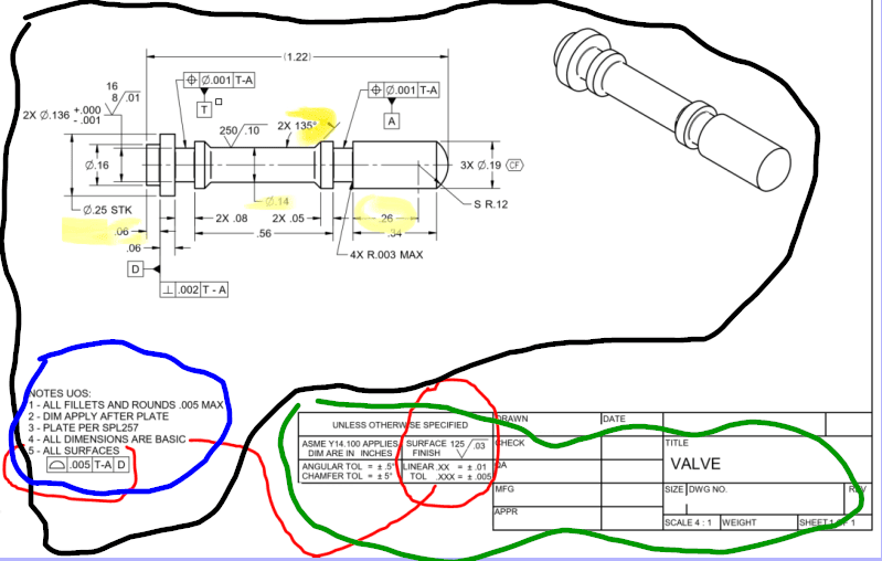
1.) If drawing shows ASME Y14.100 only, should I understand that rule#1 is enforced? Or only if ASME Y14.5 invoked directly (shown on the face of the drawing) implies envelope principle being in charge?

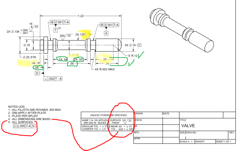
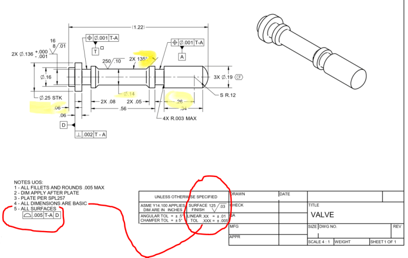
2.) How to interpret what tolerances are applicable to the dimensions in yellow:

a.) 135° angle is basic or is subject to angular tolerances shown in the title block ±5°
b.) Which dimensions are subject to linear tolerance xx = ±.01 and xxx = ±.005? I underlined in yellow some of the examples, but you can chose any dimensions shown on this print.
c.) By the same token as point b.), which dimensions are subject to chamfer tolerance = 5° (title block tolerance)? Is ±5° tolerance applied to 2X 135°?

Full disclaimer. This drawing is from an ASME training material from a rebutable source (and I am NOT assuming "the source" is NOT correct), therefore I am not thinking that the source/the author is not aware about the Y14.5 statement on 2.1.1.2 /ASME Y14.5-2009

b.) specifying on the drawing (or in a document referenced on the drawing) a general note such as: UNTOLERANCED DIMENSIONS ARE BASIC. See Fig. 7-1, illustration (c).
NOTE: Where using this method a plus/minus general tolerance is not allowed.


or 5.1.1.2 from ASME Y14.5-2018
b.) specifying on the drawing (or in a document referenced on the drawing) a general note such as “UNTOLERANCED DIMENSIONS ARE BASIC.” See Figure 10-1, illustration (c).
NOTE: When using this method, a plus/minus tolerance is notallowed via a general tolerance block or notes.


QBD_-_Copy_-_Copy_-_Copy_vpfukd.png
 
Replies continue below

Recommended for you

Hi, aniiben:

BASIC dimensions by themself have no tolerances. The default tolerances in your title blocks do not apply to them. You will need to evaluate them according to note 5.

Best regards,

Alex
 
For this drawing's specifications to be unambiguous, there should have been no general ± tolerances in the title block (or notes).

aniiben said:
This drawing is from an ASME training material from a rebutable source
Is this print from a reputable or rebuttable source?
If reputable source, perhaps part of the purpose of the example was to demonstrate this exact problem?

The note "ALL DIMENSIONS ARE BASIC" is also technically incorrect, because there are dimensions clearly indicated not to be basic: a quick glance reveals 2 toleranced diameters, an overall length indicated as reference, a stock dimension, and a single limit radius that applies in 4 places. A better note would start with "UOS" or state "UNTOLERANCED DIMENSIONS..." which would indicate more clearly which dimensions are to be considered basic.
 
Burunduk,

I don't agree with your assessment in at least in one point. If you remove the linear tolerances then how would you understand 3x Ø19 CF dimension? At least know (without removing it) I would say Ø19±.01 applies. I don’t think CF used with the profile|.005|T-A|D| is the right thing to do.
Then would you understand Ø16, Ø14 for the outside diameter as being basic?
I highly doubt that is the correct way to read this print. Not sure you agree 26 should be interpreted basic, also maybe 34, but not .06.
Which IS the rebuttable or reputable source (whichever you prefer)?
 
Hi All,

It's almost as if this drawing was designed to stir up debate ;^).

I agree with Burunduk that the note should say that all untoleranced dimensions are basic, not all dimensions. I also agree with greenimi that the <CF> annotation would only make sense if the .19 diameters are directly toleranced, not if they are controlled with basic dimensions and profile.

It appears that the drawing was originally made with directly toleranced dimensions and default tolerances in mind, and then notes 4 and 5 were added without really considering the conflicts that are created.

Evan Janeshewski

Axymetrix Quality Engineering Inc.
 
greenimi,
I agree that a CF symbol has no place near a basic dimension, but what would be the unwanted consequences of the other dimensions you mentioned being interpreted as basic? Specifically:

greenimi said:
Then would you understand Ø16, Ø14 for the outside diameter as being basic?
Why not?

greenimi said:
Not sure you agree 26 should be interpreted basic, also maybe 34, but not .06.
.26 which locates the center point of the spherical radius is probably the dimension that needs the most to be basic. .34 should be too, and why not the two .06 dimensions?

Even with the CF problem, I would still say that the general ± in the title block contributes more to ambiguity than to making the drawing well-defined.
 
Burunduk,
Regarding .19 inches diameter (the one with CF modifier) if its tolerance is changed to a plus/minus, then what would be its location tolerance to the rest of the part? The 3 diameters mutual relationships is controlled by CF, but not to the DRF of the part, right?
Would you, in this case still apply the general profile or you would say that the drawing is incomplete?
Which is your opinion?

All the other dimensions could/should be basic (.06, .14 diameter) only because the drawing is not interpretable otherwise, unless you are going to say that the drawing is incomplete (which defeats the purpose of the general profile).
Why do we need the general profile tolerance if the drawing is still incomplete?
 
greenimi,
If the ⌀.19 diameter of the interrupted feature is to be interpreted as ± toleranced, then it's location is undefined, other than as you noted, the internal location between its segments which would be governed by CF (and it's meaning regarding rule #1).

If the feature is controlled by the general profile, it's location and orientation limits are defined relative to the T-A, D datum reference frame, and also the size and the form are under control by the same profile tolerance. The power of the general profile tolerance when it is related to a DRF is that it can fully define any feature as long as the feature is not partially defined by other tolerances. If the feature already has a partial definition of tolerances such as a size tolerance for a FOS without a tolerance of position, then the general profile can no longer control it, since the size dimension is not basic, and the feature is "otherwise specified", while a useful specification of a general profile tolerance is "UOS" (and not as shown in the example at question). UOS is necessary so that features are not over-defined, or have conflicting requirements, and so that the general profile tolerance is not redundantly applied to them.

If the drawing is made so that we don't know which general tolerance is applicable for a feature, the ± from the block or the profile of a surface from the notes, then the drawing is asking for trouble. And it's non-compliant to Y14.5 as also indicated by the OP.
 
Hi All,

I agree that the presence of both a general profile tolerance and title block tolerances creates ambiguity. I don't think that Y14.5 provides much guidance on what would take precedence over the other. On the one hand, we could say that the part must conform to all of the specifications on the drawing. On the other hand, Y14.5 has examples in which a profile tolerance requirement is affected (made looser) by the presence of a directly toleranced dimension.

One additional difficulty with this drawing is that the general profile tolerance is relatively tight. Usually the general profile tolerance is a loose tolerance that can be applied to all of the features on the part. Then tighter tolerances are applied to the functionally important features. This drawing generally does the opposite.

Take the example of the .14 diameter. If the general linear tolerance was applied, the diameter would have a tolerance of +/- .01. If the general profile zone was applied, the .005 thick profile zone would control the diameter within +/- .005. The general linear tolerance would be looser than the profile requirement for most of the dimensions.

For the 135 degree angles, it's a different story. The +/- 0.5 degree angular tolerance would actually control the cone angle much more tightly than the .005 profile zone would.

Default linear and angular tolerances can be troublesome in themselves, and even worse when combined with a general profile tolerance.

Evan Janeshewski

Axymetrix Quality Engineering Inc.
 
Burunduk,

I didn't see your latest post until I submitted mine.

I'm not sure that we can say that the presence of a directly toleranced size dimension means that the profile tolerance can no longer control the feature at all. It would be great if this were true - that only basic dimensions would be allowed with profile. But I would say that Y14.5 gives other conflicting indications, by showing examples in which a directly toleranced dimension is used in conjunction with a profile tolerance. The implied result is that the directly toleranced dimension somehow makes the profile zone transform in a certain way while keeping the other basic relationships. I wish that it weren't this way, believe me.

Also, a directly toleranced size dimension does not affect the basic location and orientation of a feature when a position tolerance or runout tolerance is applied.

Evan Janeshewski

Axymetrix Quality Engineering Inc.
 
Evan and Burunduk,

Thank you for your answers.
Here is the issue (another issue) I can see (in top of the ones you guys already identified above): We agreed that the spherical dome (SR .12) should be toleranced with profile so, consequently SR.12 is basic, .26. .34 as well, but then (again of the fact the spherical dome is subject to the general profile|.005|T-A|D|) the other dimensions should/shall be basic too, including some of the regular features of sizes such as .06 and 2X.08 and .56 and 2x.05.
(green circled in my adjusted picture)
I am saying this because the basic chain dimensions should/shall come from the datums (in this case datum D). So, my point is, BECAUSE we are forcing the spherical dome to be profiled (general profile|.005) then other dimensions (again regular feature of size dimensions) now CANNOT be ± (direct toleranced). Or they can be?
The width of those grooves and the width of those tabs (to build the chain to datum D) are artificially forced to be basic.
Otherwise, how we can tolerance them with ± -plus-minus- (and maybe even add a position callout to them), but the same dimensions are basic to fulfill the requirements of the spherical dome profile?
My point is, by using the general profile (in the UOS general note), you are going to automatically force other dimensions to be basic and cannot use ± anymore (even those features are rFOS)-regular features of size-

Again, or maybe those dimensions are ± for the size, but the same dimensions are basic for the profile? How that works?


QBD_-_yiuqyd.png
 
Evan,
According to my understanding, a profile tolerance zone is based on a true profile, and a true profile is based on basic dimensions, or the CAD profile if one is part of the definition and is referred to as the source for basic dimensions.
Also, profile is a surface control, therefore unlike in the case of position, it requires the surface (and not the axis or center plane) to be basically defined. Runout is another story because it has no ability to control size. For example, total runout on a cylinder is practically similar to profile of a surface with the dynamic modifier and the same datum reference(s), but unlike profile it doesn't require a basic diameter because there is no true profile from which that tolerance zone begins to transform.

I know there are examples in Y14.5 where profile is used in conjunction with directly toleranced dimensions. If you mean examples such as 11-32 then I would say there are two completely different requirements described: a directly toleranced size requirement on the FOS constructed of the two parallel planar surfaces, and a profile tolerance on the top planar surface (which is by coincidence also part of the FOS that is controlled by the size tolerance).
The profile of a line requirement acts essentially as EACH ELEMENT parallelism tolerance. It is even stated in 11.9, with regard to the 11-32 example, that "the datum feature references can only constrain the rotational degrees of freedom for the profile of a line tolerance".
This means that the size dimension of 80±0.2 is not in any way a part of the definition of the profile of a line tolerance zone.
The basic dimensions that define the true profile in this case are implied. It is a basic 0° relative to datum A, and basic 0° of the line-sampling direction relative to datum B.
There is also the example of a directly toleranced diameter for a circular element on the edge of a cone combined with a profile of a surface tolerance on the cone in figure 11-19, but this one is still sufficiently basic-dimensioned for the profile tolerance to be able to work - the basic 15° included angle is the basis for the true profile. It is different from having a directly toleranced diameter for a cylinder and expecting the general profile tolerance to control that feature.

Here is another point that can be discussed:
Evan said:
Usually the general profile tolerance is a loose tolerance that can be applied to all of the features on the part
(Emphasis mine)

I would say that the above is correct in the case of a datumless all-over profile of a surface as a general tolerance requirement.
It is much less relevant to a general profile of a surface with a defined datum reference frame and a "UOS" in the notation (and although UOS is not part of the note in the example, I think it is generally better to include it in that type of general profile specification). I would say that the latter type of general tolerance still should be the largest tolerance on the drawing from different reasons, but it does not apply to all of the features on the part.

And even another point:
Evan said:
For the 135 degree angles, it's a different story. The +/- 0.5 degree angular tolerance would actually control the cone angle much more tightly than the .005 profile zone would
I would say that a direct tolerance on an angle can be of a tight (small) value, but it can't really impose a "tight" control on the angle, because of the ambiguity of how that angle should be evaluated on an imperfect feature. But that's a whole different topic that could probably fill a separate thread or two.

---

greenimi,
In the example, as long as the note number 4 is there, there is no reason to consider any of the dimensions you circled in green as directly toleranced. Because note 4 is there, If any of these dimensions should be directly toleranced, the ± symbol and tolerance value have to follow the dimension value so that there is no conflict with the note. In that case, a basic bypass has to be implemented to skip the toleranced dimension in the basic chain of dimensions from datum feature D to the spherical radius or any other feature controlled by the general profile.
 
Burunduk,

Burunduk said:
If any of these dimensions should be directly toleranced, the ± symbol and tolerance value have to follow the dimension value so that there is no conflict with the note. In that case, a basic bypass has to be implemented to skip the toleranced dimension in the basic chain of dimensions from datum feature D to the spherical radius or any other feature controlled by the general profile.


So how your proposal would look like?
The overall dimension (1.12 to the base of the spherical dome) would be basic, but some of the individual chain dimensions are directly toleranced dimensions?
I understand that: basic dimension (BD) + basic dimension + BD + BD = Basic dimension (BD). That is clear and there is no issue in the interpretation.
But if one of those basic dimensions in the chain is now DT (direct toleranced dimension), how the chain would work?
So it looks like DT + DT + DT + BD = BD
Fig 5.4 and 5.5/ 2018 are clear (I think) and everything is basic and no tolerance accumulation, but now if one (or multiple) dimensions are DT then how the chain would look like.
We might end up in a case where the very same dimension is DT (and it is rFOS) and it is also BD (in order to complete the chain correctly)
 
Burunduk said:
.......then it's location is undefined, other than as you noted, the internal location between its segments which would be governed by CF (and it's meaning regarding rule #1).
Burunduk (Mechanical)18 Mar 23 14:18


Burunduk,

One more question (or two):
I see that you "voted" for an incomplete drawing, right?
But isn't it that fact (incomplete drawing) in conflict with the entire concept and purpose of the general profile? To make the drawing complete.
So, now, even if we have general profile tolerance in place/ in effect, the drawing is still incomlete (location undefined), isn't it?

 
greenimi,
Only basic dimensions can be a part of a chain of basic dimensions from a datum feature to the profiled feature. Sorry if I'm stating the obvious or missing the point you are trying to convey here, but anyway: If the feature is directly connected to the datum feature by a basic dimension, there is no need to consider a chain of dimensions. I'm not sure what 1.12 is. According to my calculation, the distance from the shoulder identified as datum feature D to the center point of the .12 spherical radius is 1.04, and the distance to the external tip is 1.16. My solution would include either of the two dimensions as basic. That and the basic R.12 would make basic definition of the spherical feature relative to the DRF complete. Then any intermediate dimensions can be directly toleranced if appropriate. Generally though, even if the link from a toleranced feature to the DRF defining features is less direct, different arrangements of dimensions can be implemented as long all the linking dimensions are basic.

I didn't exactly "vote" for an incomplete drawing, but the drawing can indeed be considered incomplete as long as some of the diameters are not considered basic. This is the result of the ambiguity caused by the double general tolerance: the profile and the plus and minus. It's because of the mistakes made by the drawing maker, not because a general profile with a defined DRF is somehow insufficient or not effective enough for its purpose. With the interpretation that all untoleranced dimensions are basic unless otherwise specified, including the diameters, I would say the drawing is complete. The only problems are the meaningless CF symbol as it's placed next to a basic dimension, and the use of the plus and minus tolerance block, which creates conflict and redundancy. If I received this drawing to work by, I would explain the issue to the drawing provider and simply ask if it is possible that those will be removed, if the intent is to let the general profile to control all the features that miss other tolerance specifications.
 
Burunduk,

You fail to answer my question on how to deal with the situation when some of the regular FOS are dimensioned with ± (direct toleranced dimension, DT)?
Let's pretend .06 is NOT basic, but .06±.01 (not from the title block, but directly shown on the drawing as .06±.01)--"delete the linear .XX = ±.01 from the title block field)
Also 2X.08 is 2X.08±.01,
.56 is .56±.01
then how YOUR BASIC 1.04 would look like?

And by the way, since you asked, my 1.12 is to the base of the spherical dome, where .34 dimension is pointing (but if you like we can use YOUR 1.04 dimension for this discussion and not using mine 1.12, does not really make any difference for what I am asking)

(.06 +.08 + .56 + .08 + .26 = 1.04
.06 +.08 + .56 + .08 + .34 = 1.12)

So, again, assume the linear tolerances from the title block is deleted and some of the rFOS are toleranced with DT (direct tolerance)
My question above still remain unanswered. I honestly do not know the answer.

Burunduk said:
This is the result of the ambiguity caused by the double general tolerance: the profile and the plus and minus.

Based on your above statement, my point, again, is that the ambiguity is not ONLY caused by the double general tolerance: the profile and the plus and minus, BUT the ambiguity is caused by the combination of ± and profile. General profile or general ± has nothing to do with the ambuguity. Because ambiguity is already created or is present even if ± is attached to the dimension directly.

I expect you to not agree with me, but I am willing to learn from you. So, Thank You.


greenimi,
I did provide you relevant answers at the 15:39 post:
"My solution would include either of the two dimensions as basic." That one was referring to 1.04 from datum feature D to the center of R.12 or 1.16 to the tip of the feature.
Another answer is:
"Generally though, even if the link from a toleranced feature to the DRF defining features is less direct, different arrangements of dimensions can be implemented as long all the linking dimensions are basic".

So using your example where .06, the two groove widths of .08, and the .56 distance between the grooves become directly toleranced, the dimensions .26 and .34 would have to be removed, because they become non-useful as basic dimensions since they are given from a surface that is not basically defined relative to the DRF. Then, either the 1.04 or 1.16 are given as basic from datum feature D or the 1.12 which you proposed, also as basic.

greenimi said:
Based on your above statement, my point, again, is that the ambiguity is not ONLY caused by the double general tolerance: the profile and the plus and minus, BUT the ambiguity is caused by the combination of ± and profile. General profile or general ± has nothing to do with the ambiguity. Because ambiguity is already created or is present even if ± is attached to the dimension directly.

As you expected, I disagree.
± and profile, including a general profile specified in a note, can co-exist side by side if the designer makes a drawing that is clear about which tolerances apply to each feature.

The ambiguity is there because of a combination of practices that can't be combined:

1. There are untoleranced dimensions which are not enclosed in a rectangular frame to indicate that they are basic, and the drawing includes a note stating that "ALL DIMENSIONS ARE BASIC" (which is obviously false, but let's assume for a moment that the intent was "UOS, ALL UNTOLERANCED DIMENSIONS ARE BASIC").

2. Another note includes a general profile tolerance, which needs the basic dimensions (the untoleranced ones) to work.

So far, everything is good. The trouble begins here:

3. there is the general ± tolerance block, which is also associated with the same untoleranced dimensions.

As a result, you can't tell how to treat the untoleranced dimensions - do they provide the basic definition to features, making them controllable by the general profile, or does the ± tolerance apply to them? Is there a defined true profile so that the general profile tolerance can work, or are basic dimensions missing? Can the same dimensions be interpreted as basic for the general profile and as toleranced by the plus and minus block, and do the double requirements make sense? A lot of conflict/redundancy/ambiguity.
 
The figures in the ASME Standard are intended only as illustrations to aid the user in understanding the practices described in the text. See § 1.4.8 of ASME Y14.5 2018. We see in each technical point the picture associated in this form for exemple (fig.21) .
Second point, when you read a drawing there are a sequential rule to that.
Eyes sweep in first the body of drawing (area BLACK), second the notes in the body, (area BLUE), in this moment if an informations are missing go in the title block datas. (area GREEN),
In your case it's the "NOTES UOS" must be used.

eye_sweep_uhngoq.png
 
Status
Not open for further replies.
Back
Top