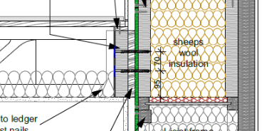
Apologies for any terminology errors here and I am in the UK so it may differ from the US but the attached diagram should help. I am looking to justify the capacity of screws through a 45mm thick LVL ledger beam (supporting floor joists) to a rim beam spaced apart by 12mm OSB and 25mm battens. I can't find any references for doing this. One reference just said that screws should not be used in multiple shear plane applications - so does that make this detail impossible?
Navigation
Install the app
How to install the app on iOS
Follow along with the video below to see how to install our site as a web app on your home screen.
Note: This feature may not be available in some browsers.
More options
You are using an out of date browser. It may not display this or other websites correctly.
You should upgrade or use an alternative browser.
You should upgrade or use an alternative browser.
Ledger beam connection through battens and OSB to rim beam 3
- Thread starter phuduhudu
- Start date
- Status
- Not open for further replies.
- Thread starter
- #2
What are the battens doing? I'm afraid your detail isn't quite clear. The OSB doesn't worry me, but something in the small screenshot isn't adding up. Why does it look like you have an I-joist, but in weak axis orientation (assuming this is a section view of the floor to wall connection).
- Thread starter
- #4
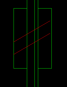
The battens are 50x25mm vertical counterbattens at the vertical stud locations to allow for a service void inside the OSB airtight layer. Then the LVL ledger beam is fixed through both of those into the inner LVL rim beam. There are metal web I joists. Below is a 3D cutaway view without the OSB and counterbattens

-
1
- #5
So realistically the screw itself never has to span a gap? It's solid wood all the way from head to tip? In that's the case, I'd likely be providing the proper embedment into the final intended bearing layer and otherwise ignore the rest as just a thicker rimboard. This assumes the battens and OSB are nominally fastened to the substructure.
- Thread starter
- #6
There are no gaps and the screws will be 6mmx140mm Heco Topix screws which have a thread that draws the members together. I was hoping I could treat it all as a thicker rim board but I was given pause for thought by a Eurocode 5 timber design textbook that said screws were not suitable for connections with multiple shear planes.
-
1
- #7
phuduhudu said:screws were not suitable for connections with multiple shear planes.
As jayrod mentioned, the battens and OSB must be nominally fastened to the substructure. In other words, they are already behaving as a single member due to fastening elsewhere. If these screws are the only things holding the batten to the OSB and the OSB to the substructure, then you're concerns would be valid and it wouldn't work.
- Thread starter
- #9
Thanks phamENG. The OSB is certainly fixed to the substructure at 300mm centres and the vertical battens are also fixed through the OSB to the substructure again at 300mm centres (in between) but does that mean I need to check the ledger beam capacity as if it was just connected to the batten, then the batten as if it is just connected to the osb and then the osb to the rim beam? I am not sure that would work.
No, since the battens and OSB are nominally fastened on their own, i.e. the screw doesn't need to carry their weights/loads as well, then I wouldn't concern myself with them, I would just ensure that the appropriate embedment in the wall studs is provided for whatever load you need.
To me, that makes sense from their standpoint. Covering their ass in a sense.bones206 said:I've been advised by Simpson that for this type of condition, they require the intermediate layers to be fastened with capacity for the full load - not just nominal fastening.
The OSB doesn't concern me in the least. The battens are the only ones that really give me a bit of pause. But I'd expect that the series of screws from the vertical battens to the studs would have capacity for the total load of the ledger bolt when taken into account all working together.
- Thread starter
- #14
The battens will also be screwed through. It just seems strange that you would count a screw that starts in the batten and goes through the OSB into the structure as effective but not one that starts further in at the ledger beam and still goes through the batten and the OSB into the structure. Surely they will both be effective? I just can't find any method of verifying their capacity by calculation.
-
1
- #15
Phuduhudu:
In some fashion, the structural screws/lag bolts are cantilevering out from the primary structural beam/inner rim board to carry your ledger beam. And, they pass through several layers of materials of questionable structural integrity. I would prefer cutting the battens off/out so that the ledger beam can bear tight up against the OSB; even better, cut the OSB out too, so the ledger bears directly against the primary LVL beam. Draw a FBD of that screw, it needs a certain penetration into the primary LVL beam just for tensile holding power, and generally discounts the first .25" +/- of length at its tip. Then it cantilevers outward off that primary LVL beam. At each of the outer mat’l. layers this canti. is supported by a spring reaction at the OSB and at the battens and finally loaded downward at the ledger beam. At each layer there may be some slop in the screw hole sizes and there may be some bearing crushing when the screw is loaded. Thus, there can be considerable vert. movement in the total joint as the number of layers increase, it is difficult to pin down how much each layer carries/supports (its stiffness as the spring reaction) and worst off all, the canti. length increases too. I think their admonition about the number of shear planes (faying surfaces) relates mostly to the above issues, certainly the screw is not stronger because it is in double shear, or some such. Finally, it is just tougher to draw the total joint tight, with screw tension, as the number of layers increases. Take a look at the AF&PA Design Guide #6, “Prescriptive Residential Wood Deck Construction Guide,” it has some good detailed discussion on ledger beams and screw locations in them (spacing, edge dist., etc.). Most good wood design texts cover these subjects too, but I doubt that you will find anyone giving you the spring stiffnesses for those screw canti. reactions. That’ why they say/imply..., get the ledger right up against the primary beam, by saying not several shear plains away.
In some fashion, the structural screws/lag bolts are cantilevering out from the primary structural beam/inner rim board to carry your ledger beam. And, they pass through several layers of materials of questionable structural integrity. I would prefer cutting the battens off/out so that the ledger beam can bear tight up against the OSB; even better, cut the OSB out too, so the ledger bears directly against the primary LVL beam. Draw a FBD of that screw, it needs a certain penetration into the primary LVL beam just for tensile holding power, and generally discounts the first .25" +/- of length at its tip. Then it cantilevers outward off that primary LVL beam. At each of the outer mat’l. layers this canti. is supported by a spring reaction at the OSB and at the battens and finally loaded downward at the ledger beam. At each layer there may be some slop in the screw hole sizes and there may be some bearing crushing when the screw is loaded. Thus, there can be considerable vert. movement in the total joint as the number of layers increase, it is difficult to pin down how much each layer carries/supports (its stiffness as the spring reaction) and worst off all, the canti. length increases too. I think their admonition about the number of shear planes (faying surfaces) relates mostly to the above issues, certainly the screw is not stronger because it is in double shear, or some such. Finally, it is just tougher to draw the total joint tight, with screw tension, as the number of layers increases. Take a look at the AF&PA Design Guide #6, “Prescriptive Residential Wood Deck Construction Guide,” it has some good detailed discussion on ledger beams and screw locations in them (spacing, edge dist., etc.). Most good wood design texts cover these subjects too, but I doubt that you will find anyone giving you the spring stiffnesses for those screw canti. reactions. That’ why they say/imply..., get the ledger right up against the primary beam, by saying not several shear plains away.
- Thread starter
- #16
Thanks for the thoughts dhengr. How about this for a thought experiment.
A 6mm screw through the LVL ledger into a 25x50mm batten can take 1kN. A 6mm screw from the batten into the OSB board can take 0.6kN and again 0.6kN from the board into the final LVL support. If I screwed each layer with a screw for each shear plane as I went out then you would say that I have a capacity of 0.6kN for the total assembly. I would have thought that rather than using 3 separate screws for the 3 shear planes you would get even better capacity using a single 6mm diameter screw through all the layers because you have the advantage of continuity requiring more hinges to form in the screw.
A 6mm screw through the LVL ledger into a 25x50mm batten can take 1kN. A 6mm screw from the batten into the OSB board can take 0.6kN and again 0.6kN from the board into the final LVL support. If I screwed each layer with a screw for each shear plane as I went out then you would say that I have a capacity of 0.6kN for the total assembly. I would have thought that rather than using 3 separate screws for the 3 shear planes you would get even better capacity using a single 6mm diameter screw through all the layers because you have the advantage of continuity requiring more hinges to form in the screw.
- Thread starter
- #17
SWComposites
Aerospace
If those battens are discrete and not continuous parallel to the ledger, then there is a risk of degradation/cracking over time (and maybe on install) thus softening the entire joint. From aerospace experience, screws/bolts do not perform well in bending, such as when there is a large shim stack in the joint, similar to this situation. If you can’t eliminate the battens, I would make the battens wider, and attach them to the rim beam with columns of screws on either side of the joists. And increase the size of the screws attaching the joists.
- Thread starter
- #19
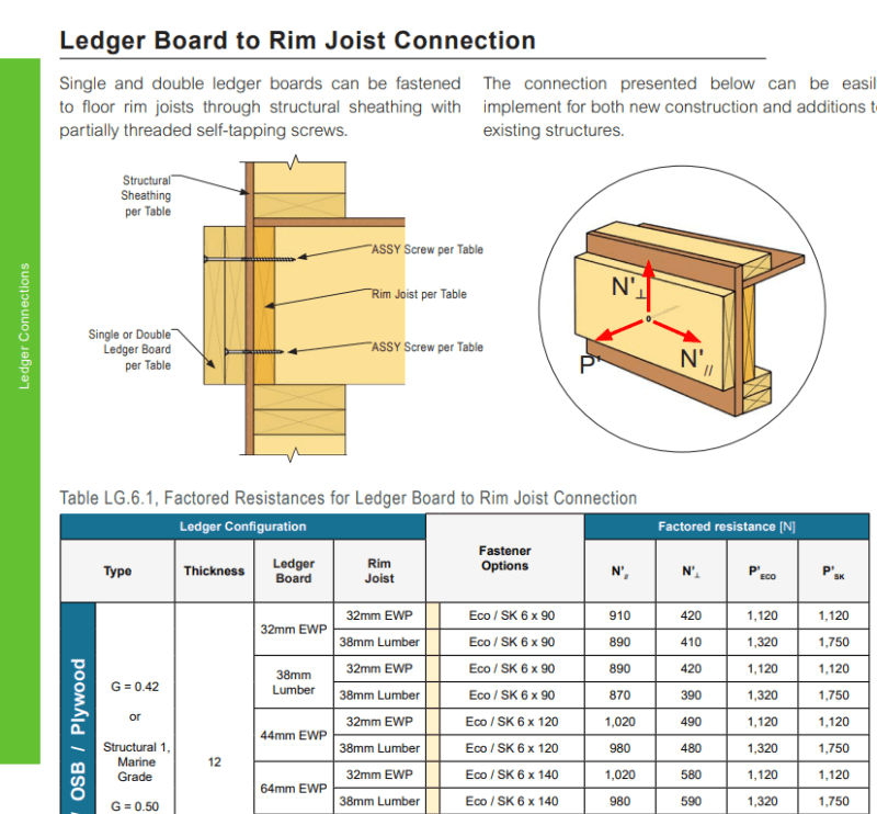
I happened to come across this from the MyTiCon connections design guide which is similar to my situation but without the additional battens so they have worked out some capacities for 90 deg connections through OSB although it can only make it better to have the connections angled.
- Status
- Not open for further replies.
Similar threads
- Replies
- 5
- Views
- 6
- Locked
- Question
- Replies
- 30
- Views
- 31
- Replies
- 16
- Views
- 17
- Locked
- Question
- Replies
- 4
- Views
- 5
- Replies
- 0
- Views
- 7