Eng-Tips is the largest engineering community on the Internet

Intelligent Work Forums for Engineering Professionals

New to GD&T. Critique my drawing

Status
Not open for further replies.

ManifestDestiny

Automotive
Feb 1, 2011
32
0
0
AU
Hi folks

I'm relatively new to GD&T (and even drawing) but after wanting to learn it for quite some time, and have taken a gentler approach of using for a personal project before I feel comfortable using it professionally (early career - so baby steps).

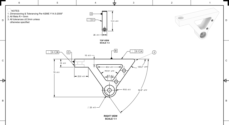
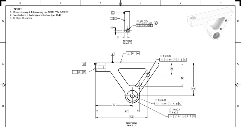
I've probably jumped in the deep end with a part that is trickier than most to dimension, so I've resolved to using the first sheet for the overall geometry and the second sheet to position holes. These are by no means a final draft, but they at least show the direction I'm going in.

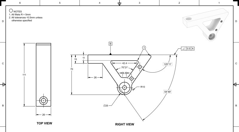
On the first sheet I'm unsure if I've dimensioned the angles on the triangular shape well enough to fully define the geometry. I'm trying to keep it as simple as possible and avoid redundant dimensions, but I'm not sure if I need more information, or if my approach is completely wrong here. I'm also unsure how linear dimensions come off a fillet edge (111mm length in the Top view).

samfr_mainframeSHEET1-1_k5haag.png


On the second sheet I've used control frames a bit more extensively to define hole positions. I just realized that I don't need a section view when a wireframe could have sufficed as well.

samfr_mainframeSHEET2-1_oxu7e0.png


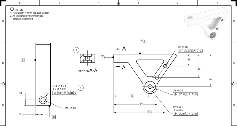
Ignore most tolerances as I'm yet to fully specify that based on what the shop is capable of.

Any advice/criticism appreciated!
 
Replies continue below

Recommended for you

Hi ManifestDestiny, welcome.

1. Maintain correct projection directions. The "TOP VIEW" should have been above the front view for 3rd angle projection and below it for first angle projection.

2. Write in a note or in the drawing frame in accordance to which dimensioning and tolerancing standard the drawing is made, and the year edition of the applicable standard. For example: "DIMENSIONING AND TOLERANCING PER ASME Y14.5-2018" or "DIMENSIONING AND TOLERANCING PER ISO 1101-2017". Which one is it?

2. When specifying datum features used as the primary, secondary and tertiary in a feature control frame, qualify them by assigning the appropriate tolerances to them. You have labeled 3 nominally perpendicular surfaces as datum features. The primary, datum feature A, should be controlled by flatness. For the secondary you called out angularity with reference to A. Which is OK, at least per the ASME Y14.5 standard, because angularity can replace perpendicularity (or parallelism) where the basic angle is an implied 90° (or 0°). However, it would be more straightforward to specify perpendicularity. The tertiary datum feature, C, has to be qualified for perpendicularity with reference to A primary, B secondary.

4. In the top view, the dimensions 10 and 13 that locate the hole from the datums have to be basic, as you are using a tolerance of position to control location.

5. Some features are not toleranced and left uncontrolled, such as the surfaces that are dimensioned by basic angles and miss a geometric tolerance.

6. It appears you dimensioned some non-critical features by dimensions shown without tolerance and specified a general +/- tolerance for them in a note. A few decades ago it would be considered OK, but these days it is no longer a good practice, although it is still done in many companies. +/- tolerances and limit dimensions are unambiguous only in certain cases, and they should be mainly used for sizes of features of size like widths and diameters. They are also used for hole depths and can define some fillets, radii and chamfers. Dimensions that define location, orientation and the shape of contoured features like the opening in the center of your part should be basic and if those relationships and properties are controlled by a general tolerance note, the general tolerance should be profile of a surface with reference to the functional datum features. It would also shorten the inspection report considerably.

7. Holes and counterbores dimensioning: you show a section view (A-A on the second page) while all the necessary dimensions are in other views. If you have no dimensions to place there, it's an indication that the view can be deleted and the general structure of internal features can be shown by hidden lines.
The diameter and depth of a counterbore, when they are part of the same callout, are written in the same row.
When a counterbore and hole are controlled by identical tolerances of position, their diameters can appear one beneath the other in the same callout (c'bore beneath hole) and a common feature control frame is placed under the 2 rows.
 
A very good start... I've seen worse from "experienced" drafters.

"Know the rules well, so you can break them effectively."
-Dalai Lama XIV
 
ManifestDestiny said:
[...] what the shop is capable of.

Draw to the final requirements, not the shop capabilities. If someone don't understand some callouts and tolerances, give them a handbook and few hours of free time to study. In the meantime outsource the work to someone who can make it.
 
Massively appreciated Burunduk

I've implemented those changes to something that's hopefully a little closer to making sense.

samfr_mainframeSHEET1-1_bwdtr6.png


samfr_mainframeSHEET2-1_f6hciu.png


You'll see I've changed to the proper Top View, but with a smaller scale to make room for all the details of the right view (is that allowed on a single sheet?). Dimensions all now carry a specified tolerance, and I managed to fix up the counterbore issue with specifying it all in the control frame, which is much clearer now I think.

Burunduk said:
2. When specifying datum features used as the primary, secondary and tertiary in a feature control frame, qualify them by assigning the appropriate tolerances to them. You have labeled 3 nominally perpendicular surfaces as datum features. The primary, datum feature A, should be controlled by flatness. For the secondary you called out angularity with reference to A. Which is OK, at least per the ASME Y14.5 standard, because angularity can replace perpendicularity (or parallelism) where the basic angle is an implied 90° (or 0°). However, it would be more straightforward to specify perpendicularity. The tertiary datum feature, C, has to be qualified for perpendicularity with reference to A primary, B secondary.

I didn't know how to specify this at first but found some examples. I'm seeing two ways of doing it, that which I've done above, and a different way like below with Datum B as an example
datumex_lefbou.png


Are these equivalent?

ewh said:
A very good start... I've seen worse from "experienced" drafters.

That's reassuring! I was actually having a chat to one of the senior engineers the other day about engineering drawing and the declining quality. I'd think the US (or where ever your location) is the same but down here in Australia most mechanical drafting is now either done by engineers who had to self learn it or it's been offshored to the third world. As a result you've either got rushed drawings by engineers (who are fitting in 20 other things they have to do) or complete rubbish that makes no sense. The only dedicated drafters left are in Civil (but thats a specialised area). Sad state of affairs.
 
Understanding the process how the part is made will help make a better drawing. If you were the machinist, what would make sense to you holding that dwg in front of you. Too many engineers don't think of it that way, they think it's not their problem.

Chris, CSWP
SolidWorks
ctophers home
 
Why is your top view rotated?
When placing views, think of them as the sides of a box and you unfold the 'box' to get the view you want to see on the drawing?

Just curious, what CAD software are you using? Siemens NX and PTC Creo will create projected views in the proper orientation from your 'base' view.

"Wildfires are dangerous, hard to control, and economically catastrophic."

Ben Loosli
 
As looslib mentioned, the top view shouldn't be rotated. Also, different views when one is the projection of the other should be in the same scale. Had the top view been in the correct orientation, you wouldn't have to reduce its scale.

The two methods of datum feature symbol attachment you are asking about are equivalent.

Datum feature C which is used as tertiary should have been qualified with reference to A primary, B secondary. Not relative to B as primary. If the datum precedence order selected for the hole positions makes sense functionally, the order should be maintained for qualifying the datum features as well.

My idea about not using the general ± tolerance note had to do with using a profile tolerance with datum references as a general tolerance and making the untoleranced dimensions basic, not about placing the ± tolerances directly with each of these dimensions, which doesn't really solve the issues associated with these tolerances when they do not define size variation of features of size, or help you with a more concise definition.

At places the definition is still incomplete and geometry can vary in an uncontrolled manner.

There are several other toleranced dimensions I would replace by basic dimensions and profile.

Some things were improved though.
 
I'd suggest to replace the "All dimensions are +-0,5" with "General tolerances acc. to ISO 2768-mK"

Also for the inner triangular cutout it's better to dimension the thicknesses and center points of the corner radii. Much easier to grab a caliper and measure a thickness than to verify a 70°21' angle... If that cut is to save weight there's absolutely no need to directly tolerance anything on that part.
 
Wuzee said:
I'd suggest to replace the "All dimensions are +-0,5" with "General tolerances acc. to ISO 2768-mK"

Also for the inner triangular cutout it's better to dimension the thicknesses and center points of the corner radii. Much easier to grab a caliper and measure a thickness than to verify a 70°21' angle... If that cut is to save weight there's absolutely no need to directly tolerance anything on that part.


Wuzee,

Two things:
1.) If the drawing is per Y14.5-2009 we are you saying to use ISO2768?
2.) ISO2768-2 (which defines geometric tolerances "K") has been withdrawn, so using an obsolete standard it is bad idea.

 
I'm following a company Engineering and Cad standard which requires us to use Y14.5 for GD&T and ISO2768 for general tolerances.
Thank you for pointing it out, I wasn't aware that 2768-2 was withdrawn. My colleague also found out the withdrawn ISO few days ago and we're thinking that the ISO 22081 is conflicting with ASME Y14.5.
What is the equivalent of ISO 2768 in ASME world? I'm unable to find a standard. We should revise our in-house standard I think.

Sorry to derail the topic, we can discuss in private messages if you'd like.
 
Greenimi -- ISO 22081 replaces part 2 of ISO 2768, which was for geometrical tolerances. But did they do away with ISO 2768-1 (for regular size dimensions)?

John-Paul Belanger
Certified Sr. GD&T Professional
Geometric Learning Systems
 
Belanger, 2768-1 is still in effect and will be replaced by ISO/AWI 2768 acc. to the iso.org website.

Burunduk,
Yes, I found that after a little search. ASME lists it as a legacy standard for historical purposes, but states that it's no longer an ASME standard.

2768-2 is indeed conflicting with ASME Y14.5 because of the difference in fundamental principals (envelope vs. independency).

My supervisor told me that ISO 2768 mk specifically was required by a late gd&t engineer in our Germany based technology center. It's not included in our standard. I assume he was used to iso more than asme and found it easier to comply (but did not realize or care about the conflict).

With B4.3 banished to the shadow realm, I think 2768-1-m still goes along with Y14.5.
 

Belanger said:
Greenimi -- ISO 22081 replaces part 2 of ISO 2768, which was for geometrical tolerances. But did they do away with ISO 2768-1 (for regular size dimensions)?


ISO 22081:2021 as indicated by Wuzhee, I think.


"This first edition cancels and replaces ISO 2768-2:1989, which has been technically revised.
The main changes to ISO 2768-2:1989 are as follows:
— tools have been added to specify a general geometrical specification and a general size specification;
— the rules for application of general geometrical specification and general size specification have
been clarified."


Wuzhee said:
......we're thinking that the ISO 22081 is conflicting with ASME Y14.5.


Well, I agree. They are two different worlds!! Do not attempt to mixed them up. My opinion.
Or your could, I guess, but you have to be carefull about the consequences.

 
J-P,
Belanger said:
Greenimi -- ISO 22081 replaces part 2 of ISO 2768, which was for geometrical tolerances. But did they do away with ISO 2768-1 (for regular size dimensions)?


I realized that I haven't directly answer your question, but I am not sure about the correct answer.
I am of the opinion that the intent is to use only the new standard (ISO22081:2021) instead of ISO2768 (even technically only ISO2768-2 has been withdrawn)
So, if would have been my drawing I would use only ISO22081 and forget entirely about ISO2768 (regardless if it is -1 -part 1 -- or -2- --part 2--)

Anyway, that standard (2768) has very limited area of applicability:

It applies to the dimensions of parts that are produced by metal removal or parts that are formed from sheet metal.

and also has that faimous clause of Rejection (which basically tells the supplier that they can produce everything they wanted with no concerns about tolerances and the customer should accept everything they are selling/ making)

"Unless otherwise stated, workpieces exceeding the general tolerance shall not lead to automatic rejection provided that the ability of the workpiece to function is not impaired"


Thanks folks, fixed the top view and ended up running this by machinists (the real trial by fire!) and they were fine with it, a generally easy part to make on a 3 axis with a slight modification to the fillets. Apparently defining a datum connected to my flatness callout that I did in the second set was strange, they'd rather see a datum clearly fixed to a surface than coming off a dimension (they'd never seen it done the other way).

Pro-tip; try and give them a DXF/DWG file of one (or all) of the sides as they can program it much faster/easier than 3D file

fraudster said:
Op - have you considered a career in retail?

I haven't, but if that's somehow relevant to the discussion, I'm all ears.
 
Status
Not open for further replies.
Back
Top