random_guy
Mechanical
I have a long (15'), thin, extrusion with cuts perpendicular to the length. Essentially as shown below.

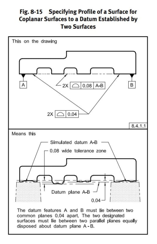
I want my primary datum to be where all the surface profiles in the image above are applied, in order to facilitate gaging of the slots to that primary datum. The top surface is also interrupted with slots.
4.12.1 (2009) specifically states "...coinciding with the datum feature simulator that simultaneously contacts the high points of two surfaces." (emphasis added).
This is also addressed in 2018 (Common Datum Features, 7.12.1) where two surfaces are again specified.
While I can see the reasoning (3 pts to form a plane), the example as given (supported on the ends) would result in sag in the center for long and thin parts, and my profile measurement would be useless. I don't see why this shouldn't be applicable for more than 2 surfaces (think surface plate inspection). The surface was one continuous surface prior to machining of the slots.
Your opinions would be appreciated!
Wise men learn more from fools, than fools do from the wise.

![[upsidedown] [upsidedown] [upsidedown]](/data/assets/smilies/upsidedown.gif)