Continue to Site

Eng-Tips is the largest engineering community on the Internet

Intelligent Work Forums for Engineering Professionals

  • Congratulations waross on being selected by the Eng-Tips community for having the most helpful posts in the forums last week. Way to Go!

Lateral restraint for columns 6

Status
Not open for further replies.

mte12

Structural
Mar 1, 2022
141
If you have a column with restraints at various levels, how do you prove that restraints are effective?

Mention is made for 2.5% of compression load, but haven't seen an example with variable compression in column with more than one restraint, as per example.

Is there an official accepted method, for determining the restraint force required to pass through each level?
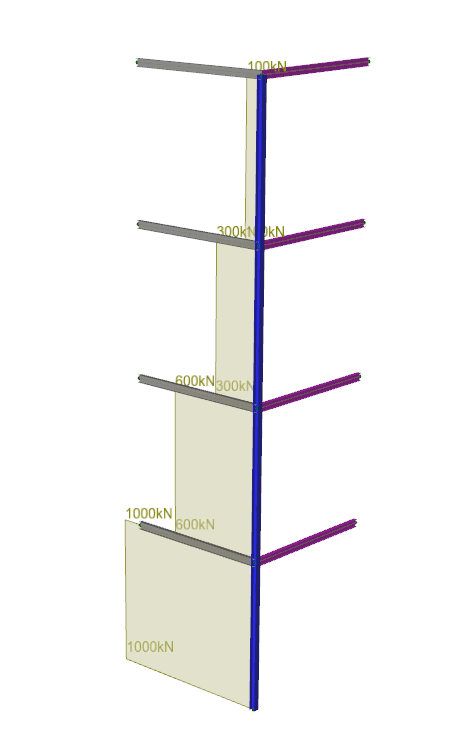
Capture_nhicb3.png
 
Replies continue below

Recommended for you

There are rigorous methods for determining the required strength and stiffness of bracing elements, but in most typical situations it is not necessary to do the calcs. If it is something that is typically done (such as what you show), you can safely assume the column is braced.

Now, if there is no floor diaphragm or roof diaphragm, the beams will see some axial load as they brace the column. But normally, these small loads will not govern, and you can just design for the lateral loads imposed on the structure (wind, seismic).

Make sure you account for P-delta effects if necessary.

DaveAtkins
 
Thanks for responding.
There is no floor/roof diaphragm, and understand that beams shown can take axial load, but there are weaker load paths following beams shown.

Please advise regarding rigorous method.
 
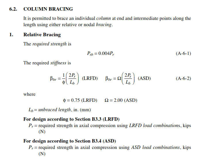
The AISC Spec. Appendix 6 is the go-to reference for this in the US. Look for column nodal bracing. Correction: it's called "point bracing" in the 2022 version. App. 6.2.2. There is a required strength and stiffness of brace.
 
My understanding is that any member capable of sustaining the 2.5% compression load is almost certainly stiff enough to act as a restraint, so the stiffness does not really need to be separately checked.
 
A rigorous method is a buckling analysis. No-one does that for a simple column bracing check.

Check your column for 2.5% of 1000kN. You could use lower values at the upper levels, due to lower axial force.
 
Thanks for responses.

AISC Specification Appendix 6, infers a required strength of 0.4% of the column load, for a relative bracing system.
Where does the 2.5% come from then out of interest?
Another reference seems to indicate 1% and 1.5% (from "The Behaviour and Design of Steel Structures to EC3, Trahair, Bradford, Nethercot, Gardner").

Also what if there is a full height end plate connection from beam to column, in the absence of elevation bracing?

AISC Specification Appendix 6
Capture2_xxbofr.png


The Behaviour and Design of Steel Structures to EC3, Trahair, Bradford, Nethercot, Gardner
Capture3_awbpgs.png
 
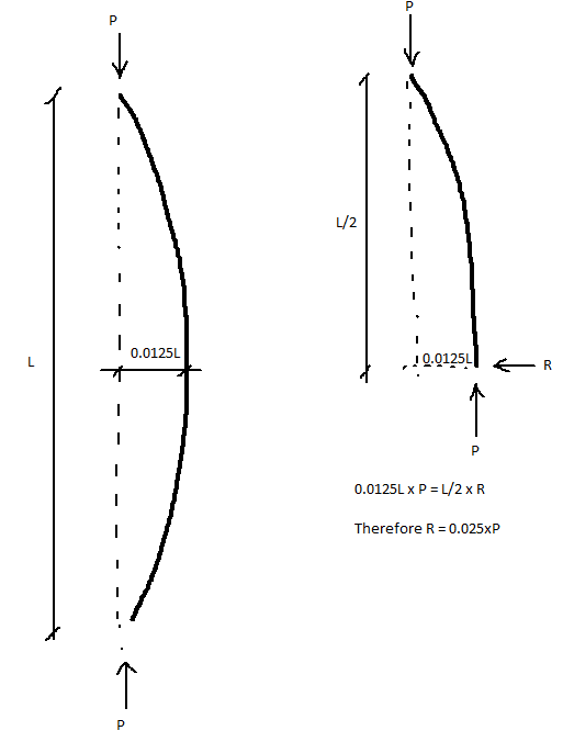
The 2.5% is the force required to resolve the lateral component of the axial force based on an assumed out-of-straightness of 1.25% of L (I think...).

In theory, a perfectly straight column requires zero force in the restraint to prevent it from buckling.
 
...wouldn't 1.25% out-of-straightness just be 1.25% lateral force?

----------------------------------------------------------------------

Why yes, I do in fact have no idea what I'm talking about
 
Some codes use 2.5%. Others 2%. It's not an exact science. It depends on various assumptions, E.g. following from bugbus's comment, a crooked column will need more bracing restraint than a perfect column.
 
JustSomeNerd said:
...wouldn't 1.25% out-of-straightness just be 1.25% lateral force?

Yes but you can have that above and below the point of restraint, so it doubles.

But again, these are all quite crude assumptions.
 
This is how I remember it when I last saw this in a textbook, but I might be missing something

Capture_tjgv1x.png
 
Thanks for responses.

As it relates to variation from a straight line, would have thought that fabrication tolerances would be similar for different countries. But there is a major difference between 2.5% used in Australia for example, and 0.4% in the US (presume I read this correct). In between there's 2% mentioned by Tomfh, 1% and 1.5% from Trahair reference.
 
bugbus said:
In theory, a perfectly straight column requires zero force in the restraint to prevent it from buckling.

Is there an out-of-plumb component in Euler's buckling equation?
 
The commentary to AS4100 (Australian Steel Code) states the origin of the 2.5% value used for AS4100: "A stiffness requirement is not given, ... This follows the finding (Ref. 15) that the stiffness requirements for centrally braced columns are satisfied by practical braces that satisfy the 2.5% rule."

In other words, there is no explicit rationale behind the 2.5% (or insert your code's number here), but these numbers have been shown to give "good enough" structures. As has been mentioned above, if you need more than "good enough" then you need to consider stiffness, not strength. Also as mentioned above, Trahair and Bradford's book ("Design And Behaviour of Structures to AS4100" or "Design and Behaviour of Structures to EC3") has a good basic introduction to how to calculate the required stiffness.
 
XR250 said:
Is there an out-of-plumb component in Euler's buckling equation?

No, it assumes an ideal column. The Euler buckling load is the point where it is easier for a perfect column to continue to shorten through bending as opposed to via further axial shortening.

Once you are modelling out plumb columns it is no longer simple Euler buckling.
 
@bugbus,
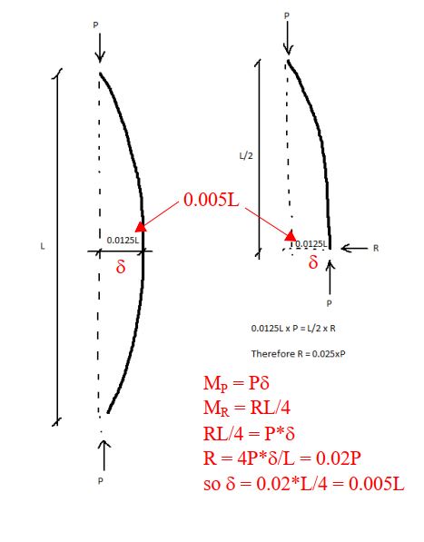
Correct me if I'm wrong, but shouldn't the moment from R be RL/4? If so, the assumed out-of-straightness would be 0.5%, not 1.25%.

Capture_tvkgqj.jpg
 
Isn’t the L dimension supposed to be the effective length, ie the lengths *between* restraints in a simply supported column? NOT the length in the absence of restraints (as the diagram above shows).
 
Status
Not open for further replies.

Part and Inventory Search

Sponsor