Continue to Site

Eng-Tips is the largest engineering community on the Internet

Intelligent Work Forums for Engineering Professionals

  • Congratulations KootK on being selected by the Eng-Tips community for having the most helpful posts in the forums last week. Way to Go!

Structural component of a beam system 2

Status
Not open for further replies.

PJMechanicalEng

Student
Nov 17, 2023
16
Hello, I need some help about this project. I need to calculate the internal forces and moment, normal stress and shear stress in the 0-45-90 strain gauge and for the linear strain gauge. However, I have doubts, especially how to calculating the shear stress and whether the internal forces are correct.
So i could make a mohr circle with the corret values. Thanks.
 
 https://files.engineering.com/getfile.aspx?folder=4e303d69-743a-42ca-8d51-374b18d7a338&file=Structural_Component_Beam_System.jpg
Replies continue below

Recommended for you

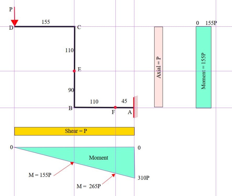
First you need to solve the system's global stuff - drawing axial, shear and moment diagrams for the system ignoring the member cross sections - just stick lines and supports.

Then you can start to look at the locations of the strain gauges on the cross sections and use your stress equations (P/A+My/I, VQ/It) to get your stresses at various locations along the member length and at different points on the cross section.

But you have to start with your global statics and force diagrams/
 
The simplest thing to do ... calculate the reactions at the gauge locations.

For the rosette, take a section ("cut") the vertical tube through the rosette location (110 mm) from the top, yes?
Now what forces/moments are here to balance the applied loads (this is called a free body diagram)
P is applied down so the reaction is P up and there is a moment reacting the offset P load = P*150mm
It's not clear, so you could reasonably assume that P is applied parallel to the vertical tube, and in the plane of the tube NA so there's no torque.
Now the "trick" is these are reactions, and the local stress is due to the local loads, ie the opposite directions (this sounds "silly" but I wanted to make the point about free body diagrams). So the loads at the rosette are ...
P compression and P*150 + moment (using the RH rule, yes?)
so now you can figure out the rosette stresses ...
45deg stress due to compression load and bending, the other two arms should be zero (I think)

If you can follow this, try the other location.


"Hoffen wir mal, dass alles gut geht !"
General Paulus, Nov 1942, outside Stalingrad after the launch of Operation Uranus.
 
Looking at your calc, I think you have the compression stress right (P/89mm2)
but you moment stress ... I think you've converted the moment arm to m (from mm) ... Keep Consistent Units !!
so the bending stress is 155*P*(10/2)/1180.75 (yeah, I use decimals as you use commas ... go figure !)
these stresses add (right?) so the strain gauge stress is ... and the strain (if you want it) is ...

The 2nd section is tricky, in that the P load is now a shear load (which the uni-axial gauge won't read, so the gauge is only reading the bending stress.

"Hoffen wir mal, dass alles gut geht !"
General Paulus, Nov 1942, outside Stalingrad after the launch of Operation Uranus.
 
Hello.

Yes P is applied parallel to the vertical tube, there's no torque.

So the for the strain gauge 0-45-90 or rosette on the cross section the total stress is:

Sigmax= -P/A - (Mfy*y)/I = - P/81 -(155*P*(10/2))/(1180.75) [MPa][/b] rb1957 I didn't understand why 155 mm? The rosette is on the surface of the retangular bar, i think the arm is 150 mm?

This Sigmay will be used on ShearStressmax={(Sigmax+Sigmay)/2 +Sqrt(((Sigmax-Sigmay)/2)^2+(Tauxy)^2)} Is this correct?


I know shear stress on the rosette section is Tauxy=(VQ/(It) My question is to know the values of V and Q and t? I is the (b.h^3)/12 correct?


In the linear strain gauge section the total stress is?

I only have Sigmax=-(Mfx*y)/I and i wich values for ShearStres=VQ/(It) V,Q and t i have to use?

This Sigmax will be used on ShearStressmax={(Sigmax+Sigmay)/2 +Sqrt(((Sigmax-Sigmay)/2)^2+(Tauxy)^2)} Is this correct? Shear stress will be Tauxy

Thanks for help


I don't know much about strain gauges, but below is a sketch showing axial and shear load as well as bending moments. Strain gauge locations are named E and F. Dimensions edited in accordance with rb1957 post following.

There will be some lateral deflection when load P is applied. That will change the geometry a little, but it is probably safe to ignore it for now.

Capture_grclst.jpg
 
isn't the offset 150mm to the edge of the 10mm wide tube ? so the offset to the axis of the tube is 155mm ... no?

is the area of the vertical 81mm2 or 89mm2 (typo in reply ??)

"Hoffen wir mal, dass alles gut geht !"
General Paulus, Nov 1942, outside Stalingrad after the launch of Operation Uranus.
 
Ok i get it, the rosette reads the deformation on the axis of vertical tube, so the arm is 155mm . Ok I think youre right.


I had an error. Area of the vertical tube is A=20x10-[(20-2x1,5)x(10-2x1,5)]=20x10-17x7=81mm2 the area is 81 mm2

rb1957 do you know how do i make calculation of ShearStress=(VxQ)/(Ixt) for this case?

V is the load P o Newton. By the formula Q=sum A'x y' My doubt is the values that a have to consider for A' and y' in Q and t for this case

The moment of inertia is (b.h^3)/12
 
there is no shear stress ... at the rosette.

Thinking about the other arms of the rosette ... the one aligned to the axis reads the normal stress (from direct load and bending).

The two arms (at + and - 45 deg) ... well they'd in accordance with Mohr's circle. Your element has one normal stress (axial) as calculated. The other normal (transverse) stress is zero. And shear stress is zero. So these two points are your principal stresses, where Mohr's circle crosses the axis. yes / So at 45 deg, Mohr's circle says the "normal" stress (as detected by the strain gauge) is 1/2 the calculated value (ie the maximum principal stress). yes?

clear as mud

"Hoffen wir mal, dass alles gut geht !"
General Paulus, Nov 1942, outside Stalingrad after the launch of Operation Uranus.
 
ok. rb1957 you say that at the rosette section, transverse stress is zero, then shear stress is zero because is hollow the vertical (retangular) tube ?

in mohr circle for rosette , then i consider tau_xy=zero right?

But in the horizontal circular tube i where i have the linear gauge section, i calculated shear stress using Tau_xy=(VQ)/(It), it's correct?


By the way, in the experimental test, on the rosette, I obtained values ​​for the deformation for each gauge, Ea, Eb Ec and I am calculating

shear stress Tau=G x Angle_xy where the Angle_xy=Ec-Ea using that Ex1=Ex*cos(teta)^2+Ey*sen(teta)^2 +angle_xy*sen(teta)*cos(teta)

for teta=zero then Eb=Ex for teta 45 e -45 e get to Ec and Ea equations, then i get to Angle_xy= Ec- Ea

with this expression i obtained experimentaly, not analytical, this values.

Load [N] angle_xy shear stress [MPa] normal stress [MPa]
5 -3,2832E-06 -0,083931429 -3,5051076
7 -3,02488E-06 -0,077327759 -4,70843832

which makes me confusion when youre saying that shear stress (analytical calculation) at rosette is zero. Because i have to compare analytical with experimental values.

by the way could you explain me, why the experimental (not analytical), are the values negative for each gauge on the rossete? it was espected obtain this values, for each gauge? do you know the reason ?

Rosette:

Load [N] gauge a [µs] gauge b [µs] gauge c [µs]
5 -14,34284 -51,5457 -17,62604
7 -20,91824 -69,24174 -23,94312


In the linear gauge, i think they are negative because of compression load right?

Load[N] linear gauge [µs] Comparator clock [mm]
5 -0,800698 1,491
7 -6,929114 1,9308
9 -12,7958 2,762


the first value could be error its very diferent from others, wich could be the cause of this -0,800698 ?

Thanks


yes, the circular tube has shear (direct shear from the load, not torque. But ...

1) the gauge is on the top CL, where shear stress is zero, and
2) a linear gauge (as you've clearly drawn it as such) cannot detect shear, only normal stress (in the direction of the gauge).

This gauge responds to the bending moment in the tube (P*265mm)

"Hoffen wir mal, dass alles gut geht !"
General Paulus, Nov 1942, outside Stalingrad after the launch of Operation Uranus.
 
Ok. I have a final doubt.

Does anyone know, how do i calculate the displacement by Castigliano theorem for this case?

Thanks

 
PJME said:
Does anyone know, how do i calculate the displacement by Castigliano theorem for this case?

This is not a schoolroom...read your bloody text book.
 
Hello again.

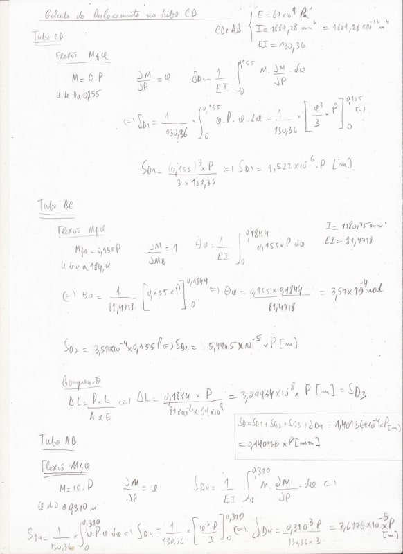
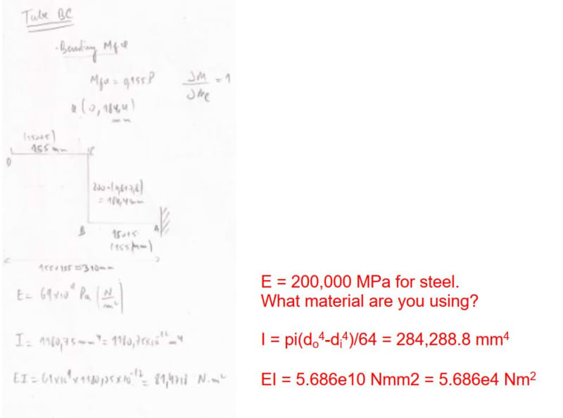
I am calculating the displacement using the Castiglian theorem as in the annex, but I am obtaining analytically for example for P=5N, a displacement of SD=0.7 mm on D position.
(0.140136x5=0.7 mm)
When experimentally, on the comparator, It obtained a value of displacement of 1.4 mm for 5 N. Can anyone help or explain the cause?

Thanks
Displacement_ietmsj.jpg
 
it is hard for me to follow your calculation, I appreciation you were just scribbling it out. Take the time to organise it, maybe use two pages ?

where do you calculate your result ? ie so with P = 5, the deflection at A is d = ...

you seem to mix units ... meters and mm. Maybe you've adjusted the index properly, maybe not ... it is often a source of error.

The horizontal segments are dominated by bending, not so sure the vertical is ??
what about displacements due to shear ?

"Hoffen wir mal, dass alles gut geht !"
General Paulus, Nov 1942, outside Stalingrad after the launch of Operation Uranus.
 
My guess is that you have not properly accounted for the change in slope at point C.

I would not use Castigliano's method to calculate deflection at D. Point D deflects both vertically and horizontally. Its vertical deflection is equal to the normal cantilever deflection of the round pipe plus the concentrated slope change between B and C times length CD. These can be calculated directly.

The horizontal deflection of point D is the slope at B times height BC plus the horizontal deflection of BC.

 
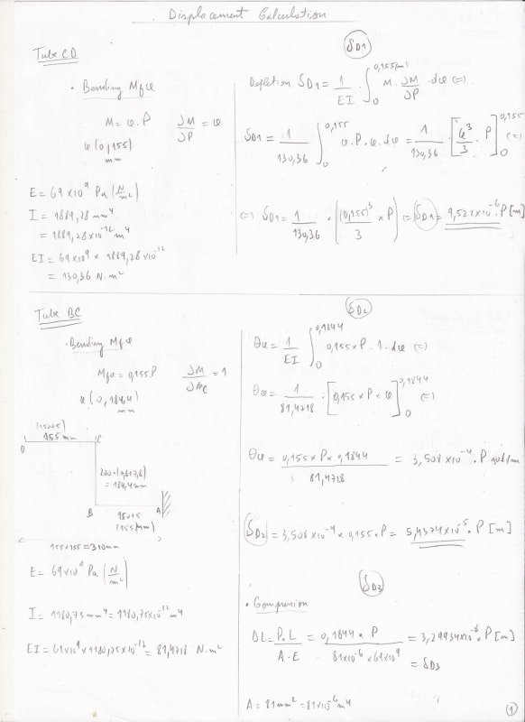
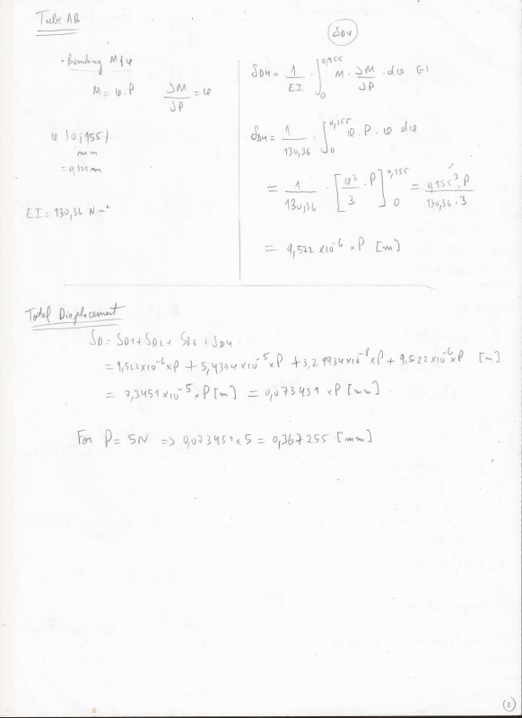
OK. rb1957 I had calculated again. i'm not considering the displacement due to shear, do you think it is significant?

Should i use Deltax=(Tau * L)/ (G *A) ?

On the AB tube:
I was using x (0 to 310 mm) on first post. But i think its (0 to 150 mm ) on AB tube. it is right?


Now for a P=5 N i have 0,367255 mm witch is very low compared to the experimental one by the comparator 1,4 mm.

Thanks

Displacement1_cymzar.jpg
Displacement2_yaaryk.jpg
 
Before we waste too much time on this, let's get some agreement on the basic material properties. For the round pipe, I can't quite make out your illegible handwriting for the value of I but what material has a value of E = 69*10[sup]4[/sup]Pa?

Capture_e0ptp6.jpg
 
Tube BC is 20x10mm with wall thickness of 1.5mm.

I[sub]minor[/sub] = (20*10[sup]3[/sup])/12 - (17*7[sup]3[/sup])/12 = 1,181mm[sup]4[/sup]
EI[sub]minor[/sub] = 200,000*1,181 = 236e6Nmm[sup]2[/sup] = 236Nm[sup]2[/sup] (for steel)

Are we agreed on the member properties?
 
Status
Not open for further replies.

Part and Inventory Search

Sponsor