Continue to Site

Eng-Tips is the largest engineering community on the Internet

Intelligent Work Forums for Engineering Professionals

  • Congratulations waross on being selected by the Eng-Tips community for having the most helpful posts in the forums last week. Way to Go!

Pipe Expansion Z-Bend Formula 1

Status
Not open for further replies.

SS_What

Mechanical
Jan 4, 2024
3
Hey everyone - I've lurked on this forum for a while, and have pulled some VERY useful information from y'all in the past, but one thing has been eluding me recently. I'm trying to recreate a spreadsheet tool I once had at a former employer that would output pipe stress for L and Z bends used for natural expansion compensation. I want to use this tool after I already have the piping layout "mostly" designed, to check where I need to add expansion compensation.

My issue: I can find in the ASHRAE books the full long form formula for L-bends that is designed to solve for the short leg if the long leg is known. I can reverse engineering this equation to solve for the "stress allowed" which becomes the "calculated stress", as I know both the long and short leg dimensions I have laid out.

Long Formula, that I can work to solve for "Sa":
L-Bend_Long_Formula_debs6z.png


It then shows a "simplified" formula for this same calculation that can NOT be reverse engineered because it assumes a reasonable "stress allowed" number to approximate the short leg that is good for carbon steel and copper piping.

Short Formula:
L-Bend_Short_Formula_sggc9h.png


However, when we jump to the Z-bend section, ASHRAE only shows the simplified formula... I want the long-form equation for a Z-bend that I can reverse and solve for the stress.
Anyone happen to have a resource that shows the full long-form version of the Z bend formula?
 
Replies continue below

Recommended for you

Strongly suggest that you abandon this ancient aproximate ASHRAE technology for flexibility evalualuation of piping systems.

I do suggest that you review the detailed methodology contained in ASME B31.1or B31.3 for your piping system !


Perhaps consider a quick accurate and automated methodology such as used by CAESAR-II analysis codes

MJCronin
Sr. Process Engineer
 
Agreed with using actual pipe stress software. In addition to knowing if your system is over stressed, you'll have support/anchor forces which are not easy to approximate on complicated systems.
 
MJ and RV - I agree with you on principle that using a software is the best way to be fully covered. However, the company I currently work for typically does smaller jobs that the ASHRAE estimated calcs with proper safety factors are more than enough.

However, I'm working on one of the largest projects they've done, and I wanted to be able to quickly check over a few things. My thought process is to use the excel tool to give me a rough level of comfort. Or, if it does NOT give me that comfort, to justify a request to purchase a proper software based modeling solution to analyze the entire building. I've used TRIFLEX in the past, not sure how that compares to CAESAR II though.

Thanks for the feedback so far!
 
The ASHRAE calculation method you show is called the Guided Cantilever Beam Method which gives a very very conservative value for stress in pipe due to thermal expansion.

In the gudided beam method the thermal deflection of a given run piping is assumed to be absorbed by the offset leg of the connecting piping. Where the offset leg of the connecting piping is assumed to act like a guided cantilever beam. A guided cantilever beam is a beam that is totally fixed at one end, and at the other end (the one that moves with the thermal expansion) can move laterally in the direction of thermal expansion, but cannot rotate. This beam type is listed in most tables of beam found in any mechanics of materials textbook. If you think about it, this is how the offset piping mostly moves when deflected but the expansion of the long run, since it is restricted from moving totally by the connecing downstream piping at the far end, but at the near end point of connection to the thermal expanding pipe it moves but does not rotate. To some extent this is true but there is some rotation of the ends but this is neglected for this analysis method.

For a guided cantilever beam experiencing deflection at one end that does not rotate with other end fixed, the moment is calculated to be:

M = 6EI(Delta)/L2

Since Stress S = Mc/I

then substituting M into the S equation

S = 6EI(Delta)/L2 * (c)/I

Since I cancels and c = D/2 the this reduces to

S = 6E(Delta)/L2 * (D/2)

S= 3E(Delta)(D)/L2

And rearranging:

L = SQRT ((3E(Delta)(D))/S) which is the AHRAE equation above.

For a Z bend thermal expansion of the lenght of the long straight run between the two short runs will be taken up equally by the short runs so in the above equation Delta = total thermal exapansion divided by two, but the same equation is used.

This link provided further discussiion of the guided cantilever method.


I have some good other personal references that I will post shortly.
 
Snickster - Thanks for the information, I appreciate it. That is much closer to what I remember. I look forwarding to see the other references that you have, if you still care to share.

Thanks!
 
I think it’s always to understand the basics using simple formulae even when they’re not precise (enough). Going the pipe stress route with AutoPIPE or CII is way too easy nowadays and gives the engineer little understanding and gut feeling to know what’s happening and take appropriate steps in the engineering process.
EN 13480, I think, has a method in one of the appendices of part 3. There are some ASME PVP Conference Proceeding papers, if memory serves me a.o. from Nicola Jacimovic.
Get a copy of Peng as that is THE basic reference for any pipe stress related discussion.

Huub
- You never get what you expect, you only get what you inspect.
 
As does B31.1

--Einstein gave the same test to students every year. When asked why he would do something like that, "Because the answers had changed."
 
I have a good reference from a Caesar seminar that I will post later today and maybe an old excel spreadsheet calculation I developed if I can find it.
 
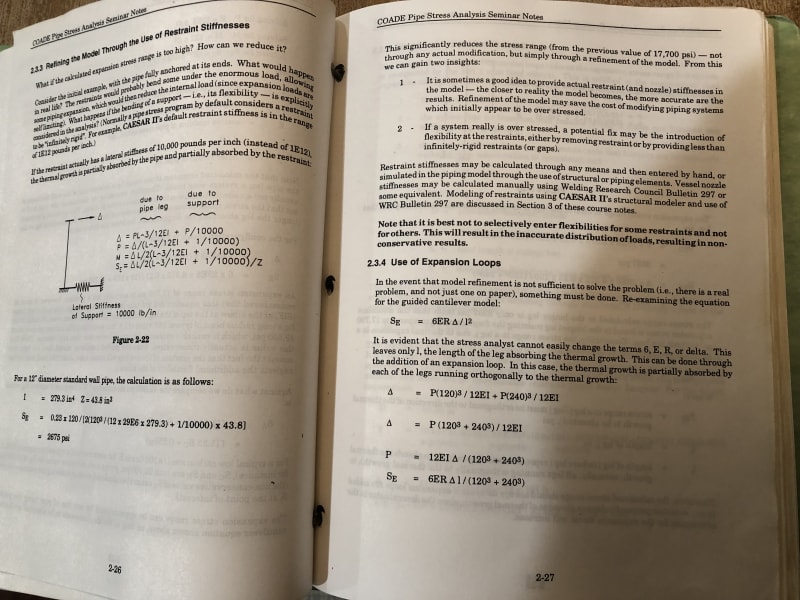
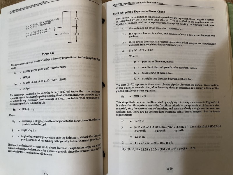
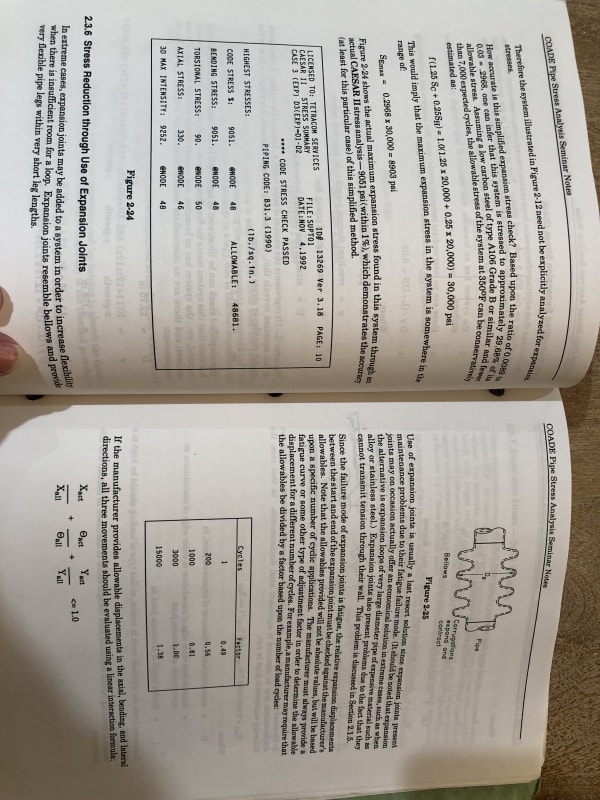
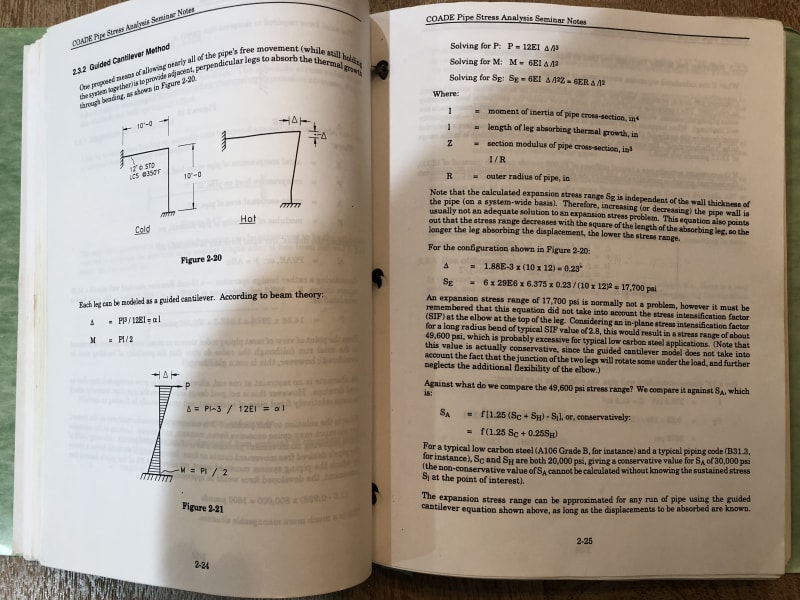
Here is pages of Caesar manual which goes over manual piping stress analysis using the guided cantilever method. Note that in their calculations they include a stress intensity factor for fittings such as elbows.

IMG_1529_aetqjq.jpg
IMG_1530_irqk79.jpg
IMG_1532_mqsuri.jpg
IMG_1528_tw0h9h.jpg
 
Helpful hint - place a black sheet behind scanned or photographed book pages to eliminate bleed-through of the reverse text.
 
Status
Not open for further replies.

Part and Inventory Search

Sponsor