Continue to Site

Eng-Tips is the largest engineering community on the Internet

Intelligent Work Forums for Engineering Professionals

  • Congratulations waross on being selected by the Eng-Tips community for having the most helpful posts in the forums last week. Way to Go!

Fixed or pinned connection 3

Status
Not open for further replies.

adrianstructures

Civil/Environmental
Jan 20, 2024
2
RO
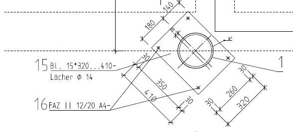
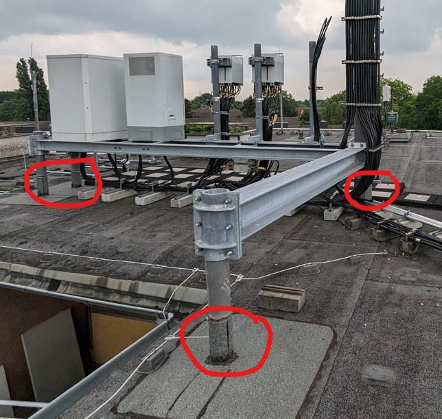
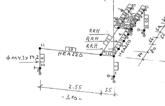
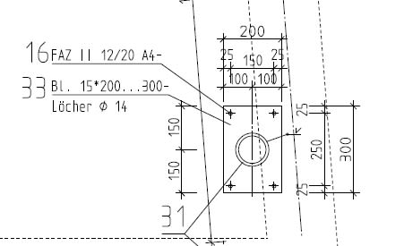
I have a question.. why do many engineers model the main mast connection as well as the other connections as being in the structural calculation model as pinned and not fixed?
3_ipnlvc.jpg
2_j5fqpl.jpg
1_tpz8zv.jpg
4_gd4tuw.jpg
 
Replies continue below

Recommended for you

Nothing is ever fully fixed, and true pinned condition is rare. Assessing the degree of fixity of connections typically takes significant effort and time to create a sophisticated analysis model. Most often, the results using the assumption of a pinned connection are conservative, but have a modest to no effect on the member sizes compared to the results of the more detailed analysis.
 
Unless the structure is unstable if base is assumed pinnned (cantilever column), it's usually assumed pinned.
You can do 2 analysis and assume fixed for foundation/anchor bolt design, some do that.
 
Agree with others. Except for cantilevers, I wish the terminology 'fixed' would go away, replaced with 'rigid'.
 

The picture ( waterproofing patches around legs ) implies the framing of the roof top units freely supported on flat roof and probably the ftgs are PC or flat plate supported on heat insulation.

Apparently , the supports ( joints 1,10,22,28 ) are pin and the others rigid connections. You cannot provide fixed support conditions here wright?


Use it up, wear it out;
Make it do, or do without.

NEW ENGLAND MAXIM


Why do we do it? Because we don't want moment transferred down into the roof slab. If we assume that no moment is transferred, the resulting stiffness of the frame is high enough that very little moment gets transferred. Of course, some will get transferred and we have to be aware of that and design for it. But no model is ever 100% representative of reality. So we make up a plausible story, create a model around it, and then make sure the actual detailing makes room for what will really happen.
 
phamENG said:
Why do we do it? Because we don't want moment transferred down into the roof slab. If we assume that no moment is transferred, the resulting stiffness of the frame is high enough that very little moment gets transferred. Of course, some will get transferred and we have to be aware of that and design for it. But no model is ever 100% representative of reality. So we make up a plausible story, create a model around it, and then make sure the actual detailing makes room for what will really happen.

I agree this is a pretty common practice, but it's a practice that is not defensible IMO. The short columns are relatively stiff and WILL transform moments to the base because, well, a dog only has four legs even if you call a tail a leg.

To ensure the bases are covered, why not just run two models, one with a pinned base and one with a fixed base and design for both conditions? Yes, that would be a conservative approach because, yes, the base is not 100% fixed, but it avoids having to determine the rotational spring constant, etc. and avoids having to defend a "plausible" story. This approach may result in anchors with more embedment or, heaven forbid, more anchors, but I think that would be more easily justified than to explain why the anchorage failed by saying you considered the base connection as a pinned connection because "everyone does that".

Just my two cents.
 
If running a second model is how you get to ensuring the detailing makes room for what will really happen, that's fine. But your method is just doing my method twice, which makes it twice as indefensible. If you really want to figure out if the dog's tail is or is not a leg, then you need to determine the axial stiffness of the tail and run a hyper accurate finite element model to capture stress in the concrete, anchor, plate, welds, column, and everything else with exacting granularity. Anything less is just making up a plausible story and creating a model around it. Or two models.

We've been down this road before. It's the engineer's responsibility to understand the structure he/she is designing and/or analyzing. If you lack the experience to know how certain joints will behave, then by all means run additional models to envelope the situation and gain a better understanding. But in practice, none of us really have the time or budgets to envelope every possible scenario in our designs. So we have to pick our battles. If my initial pinned assumption results in reasonably small rotations at the base, I'll make sure my anchor design isn't pinned to a gnat's arse and I'll make sure my plate is as thin as possible. But if you don't know what 'reasonably small' is, then yes...take the time to figure it out so you can use your "engineering judgement" in a responsible and informed manner.

Now, can we talk about that extended end plate moment connection to the pipe column? That's a nifty bit of connection design.


phamENG said:
Now, can we talk about that extended end plate moment connection to the pipe column?

It doesn't look like a moment connection to me. Looks like a stiffened clamp. I don't really like it because it seems to be relying 100% on friction, unless there's welding there that I can't see.
 
It's missing a couple bolts to fit the 'normal' configuration, but as long as the backside is welded to the column I think it could work. I agree, though, that it is pretty sketchy if it's 100% friction.
 
phamENG - I respectfully disagree with you on this one. Running two models, which is fairly easy by copying the original model and just changing the boundary conditions, envelopes all possible fixity issues at the base. It seems your definition of the "responsible engineer's understanding" may be essentially based on "it's how it's always been done before" and not with testing, etc. (i.e., actual data). Of course, I could be wrong. You could have that data at your fingertips. Most engineers don't.

You insinuate I lack experience. I certainly do not. I, too, have designed a lot of framing consisting of assumed pinned base connections. I just recently started considering the validity of this assumption primarily due to my perusal of performance based design (ASCE 41). That certainly was an eye opener for me. I also have experience observing damage as a result of the Northridge earthquake when I was asked to evaluate a roof top structure supporting a chiller. The framing was steel and the platform consisted of WF sections. Most of the beam to beam connections were the typical shear type connections with a shear tab welded to the supporting beam and 3 bolts in the supported beam. The two outermost bolts were sheared off, displaying an excessive amount of rotation. Even if you disagree with my assessment and concern, you don't need to be offensive about it.

It appears this structure is also a roof top installation. If it's located in a high seismic region, it may experience deformations well beyond the elastic range as did the frame I described above.

I do share your concern about the connection at the top.
 
I agree that running two models isn't onerous in this particular case. It's just making a copy and changing the support conditions. Adds 1 hour of work, tops.
 
SE2607 - we had this identical discussion already in another thread. I'm still not insinuating you lack experience, and I'm still not saying responsible use of engineering experience is to blindly go with the flow. As I said in my last post: if you don't understand how the joint will behave, then by all means run multiple models to envelope it. But once you've done a few of them...a pattern starts to emerge that exposes why it's been done that way for so long. You can set up a good set of guidelines for detailing that will cover most applications and save the time with no negative results.

It may only add an hour to the project...but they add up. While not as impactful to me running things solo, my last firm could have employed an extra engineer for the time it would take to do that on every project.

I went out on my own wanting to do things with greater accuracy and precision, take the time to run all the calcs that I was never able to working for somebody else. And I have...and I'm starting to see that, in most cases, there was a reason we did it the way we did. Nobody really knew what those reasons were, which is not good, but I'm finding that a lot of those assumptions can be defended with proper detailing.

Bottom line is that you have to understand how the structure will behave. Whether that is by running multiple models on every structure, or being able to intuit the results, to each their own. I do a mix of both depending on the relative risk of the design. Ground floor column of a midrise building? Sure, I'll run a couple models. HVAC rack? I'm good with one. But I don't do seismic, so if we're talking about a massive chiller on a flexible building, I'd probably go the extra mile.
 
Creating a fixed model also changes the checks to your base plate, and the supporting structure in addition to the frame.
 
phamENG said:
But I don't do seismic
Then, it probably doesn't matter what you assume, unless you are in Dade County, FL. Otherwise, you are dealing with live load, and, in this particular case, roof live load, which will only occur when the roof is re-roofed or there is a fire.

If your typical base detail considers any moment at all even though you are analyzing it as a pin connection, your anchor embedment will be greater. This might not be necessary if you actually looked at the loads based on a fixed connection.

Regardless, we obviously don't look at structural engineering the same.
 
They can be fixed or pinned... I'd usually use pinned to force the moment connection to the post and the beam over; it's likely a lot easier to accommodate. The moment comes from the lateral loading on the equipment plus what appears to be a large eccentricity.

-----*****-----
So strange to see the singularity approaching while the entire planet is rapidly turning into a hellscape. -John Coates

-Dik
 
What's it actually supported by? Before you assign a lot of moment at the base, you have to know how that will be developed. From the sketch, it looks like a few short pins connect it to a thin slab. If those drilled in anchors are going to pull out, it is foolish to depend on fixity. Too much modeling, too little common sense.
 

What I have been thinking is fixed connection transfers moment to the base hence more conservative than a pinned connection which doesn't transfer moment. Can you please explain what am I missing?
 
Status
Not open for further replies.

Part and Inventory Search

Sponsor