Continue to Site

Eng-Tips is the largest engineering community on the Internet

Intelligent Work Forums for Engineering Professionals

  • Congratulations waross on being selected by the Eng-Tips community for having the most helpful posts in the forums last week. Way to Go!

Stability Analysis for Walls/frames that support cathedral / vaulted / scissor trusses 3

Status
Not open for further replies.

StrEng007

Structural
Aug 22, 2014
521
I’ve seen a lot of discussion about scissor/vaulted trusses here and there seems to be a consensus in the overall design approach.

1. Try to restrict the truss from moving (due to truss deflection) and impart a large thrust load on the supporting structure.

2. Allow the truss to displace as a pin-roller connection and check to make sure your walls can handle the displacement.

It looks like most of you have agreed that making a structure stiff enough to withstand the required truss deflection would be a futile exercise. Also it’s not so much the type of truss connection that allows this displacement (ie using one of those Simpson “slip connections”) but rather the lack of infinite stiffness from a wall support that give you the theoretical roller (makes more sense to me with wood than the scenario I'm about to present).

In both situations, the stiffer the truss members and the less overall deflection the truss experiences, the less the horizontal reaction if the truss was pin-pin, and the less the horizontal deflection for a pin-roller.

Good so far? Is there anything I’ve misinterpreted?

Most of my projects don't utilize wood construction for the wall system. 99% of the time I have bond beam/tie beam with CMU or concrete construction. Sometimes I even have concrete portal frames as discussed below. The way I treat most of my regular truss type conditions/non-scissor type (that is, in order to stay in line with the truss designer utilizing a pin-roller approach) is to consider that most of Simpson's truss connectors will deflect in the F1 direction, no matter what the given F1 load is. Here is some language from the Simpson Catalog:
Screenshot_2024-03-18_203209_sw2pul.png


Screenshot_2024-03-18_203129_qd5kvc.png


So given the fact that a typical connector has up to an 1/8" deflection and the Truss Design Documents for typical trusses have a horizontal creep total (CT) that doesn't exceed these values, you can assume the designated end of the truss is able to displace. [highlight #FCE94F]You usually don't find engineers who are arguing that their tie-beams are laterally displacing enough to provide a roller support.[/highlight]. I realize this invalidates what some of you had said about a truss not being able to displace due to friction at the connection, or the diaphragm working in unison. To be honest, I don't know how to qualify the fact that all our truss designers use pin-roller if not for this.


So how do we handle the stability analysis in a situation like this? To better explain my situation, I’m looking to do a cathedral style roof that sits on a concrete portal frame with storefront infill below the frame. So I will have lateral loading in the plane of the portal frame (F1), gravity load from the roof truss, and an assumed F2 due to wind load on the walls (windward, leeward, side wall) in addition to a F2 from the thrust load of the truss (btw its' so interesting how all this is going on but rarely gets illustrated). With a cathedral ceiling, I don't see how I can take the same liberties that I do for typical a common truss. So how should I handle the stability analysis?

Also:
When doing cathedral style roofs:
1. Is is common for the architect or GC to put the truss designer and structural EOR in connection prior to the development of construction documents. So often I'm supposed to wait a month out until the truss design can get me the TDD reactions, and for a truss like this it's putting the cart in front of the horse.
2. Is there a better way to handle the trust reactions? I must have no tension rods, no ceiling at the tie-beam elevation, a maximum sloped vault inside the structure, no ridge beam or columns to break up the spans, and there cannot be buttresses or pier cast into the wall (ie, inside face of walls all have to be uniform).
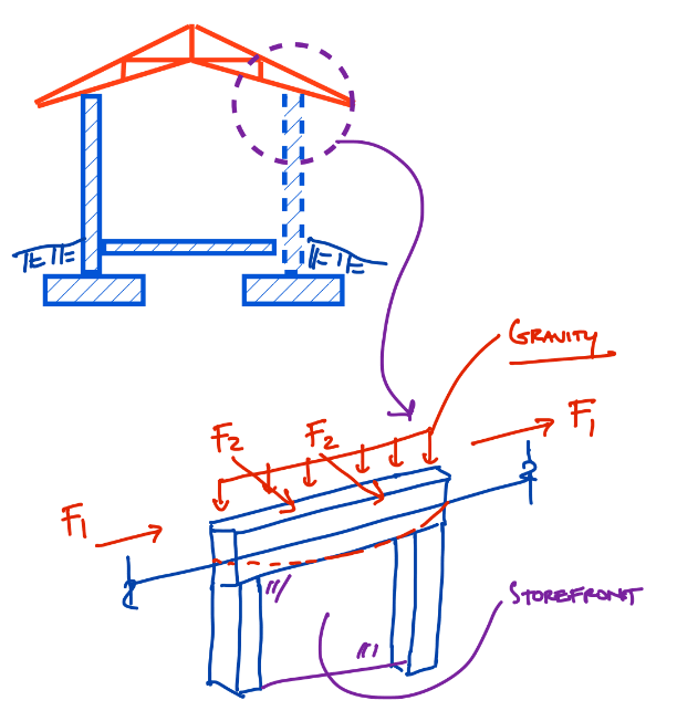
Screenshot_2024-03-18_204838_yxjxe2.png
 
Replies continue below

Recommended for you

I would design the truss to be as stiff as practical - say 3/16" max horizontal deflection each way and call it a day.
You will lose your mind (and your fee) if you try to account for the thrust.
 
XR250 said:
You will lose your mind (and your fee) if you try to account for the thrust.
Really, what gave it away? [morning]
 
I would first determine an acceptable maximum horizontal displacement of the truss as the minimum of:
[ol 1]
[li]The horiz. displacement resulting from the allowable vertical displacement of the truss (L/360 or whatever). There should be a simple geometric relationship between the vertical truss deflection, the truss slope, and the horiz. displacement.[/li]
[li]The maximum horiz. displacement that the supporting structure can tolerate. In this case, this would be your portal frames.[/li]
[/ol]

With the maximum horizontal displacement of the truss known, I would include this limit on the drawings for the truss designer to follow. I would probably determine the maximum vertical deflection which would result in this horizontal displacement, to be less confusing for the truss designer. So, maybe you determine that the truss must meet a deflection criteria of L/720 for example.

Trying to account for the relative stiffnesses of the trusses, truss connections, roof diaphragm, portal frames, and other parts of the structure would be the most correct approach, but as already noted above will likely result in you losing your mind. The design of these prefab. roof trusses is such a niche/proprietary process that even trying to account for that in your own analysis is probably not realistic.
 
It has been a long time since I dealt with a scissor truss on a project - but it was a time where I similarly lost my mind trying to chase down the thrust.

I recall that one my bigger revelations was that once I defined a maximum lateral deflection for the scissor truss, I checked the capacities of my walls to support that "deflection" as a cantilevered element. The equivalent load/moment which would create the lateral deflection was extremely manageable, and a smaller impact than my components and cladding simple span behavior.

I did continue getting lost about the effects on the truss/supporting wall at the returns of the perimeter walls, upon installation of the diaphragm and the other elements that Eng16080 mentioned - but was able to live with the approach I described above.
 
Maybe I'm not seeing things clearly here but the horizontal outward thrust of the truss will be almost zero.
This due to the fact that most "portal frames" like this have very little stiffness in that direction (i.e. outward leaning of a "wall") except perhaps near the building corners/ends where there are orthogonal frames or walls coming in.

With low stiffness, the "thrust" or force on from the wall is a low number, the portal frame will simply lean outward as there's no stiffness to resist it, thus....little or no force.

Other than that - I agree with Eng16080's approach on determining an "allowed" lateral movement based on vertical movement.

Also - as the EOR, you can always contact a local wood truss designer and ask them to run a quick truss design for you to see what sort of deflections (vert & horiz) they are getting based on your truss geometry and loads. We've done this often.


JAE, I think we're all probably saying the same thing but perhaps mixing up the terminology by not qualifying whether outward thrust means a force or a horizontal displacement (I'm probably guilty).

I agree with what I think you're saying: the portal frame (with the exception of it's ends at the end walls) will have very little stiffness, meaning that the thrust force being resisted by it from the trusses will be very small. Meanwhile, there will be a horizontal displacement which is probably very slightly less than what would occur if the support was idealized as a roller.
 
XR250 said:
I would design the truss to be as stiff as practical - say 3/16" max horizontal deflection each way and call it a day.
So, Fuhgeddaboudit?

Eng16080 said:
The maximum horiz. displacement that the supporting structure can tolerate. In this case, this would be your portal frames.
I guess this was part of my original question. I was wondering how this displacement should be tied into the overall stability analysis of my frame. I'm considering the P-Delta effect here and considering that it might be occurring in two directions. Now I've read all of your comments, and it seems like you're saying any frame displacement due to thrust ought to be disregarded.

The only issue I have with this is, I've see case studies and photos of failed church roofs where thrust and combination of gravity loads have caused total loss and subsequent collapse of bearing walls.

EZBuilding said:
but it was a time where I similarly lost my mind trying to chase down the thrust.
I've been down this path before on a couple projects where the obsession to find the true nature of the structure just ends up spinning in circles.
One thing of particular interest to me is the fact that we say our walls are braced by the roof diaphragm that is supported by these scissor trusses. More often than not, the roof sheathing is NOT in direct contact with the tie-beam (or top plate for the rest of you) and we say this lateral load makes it's way into the diaphragm via the connection between the truss and beam.

So for any given situation, windward loads put into the truss heel while the truss heel may theoretically be pushing outward due to gravity loads. I'd draw a FBD of what I'm discussing but don't have the time at this particular moment.

EZBuilding said:
I checked the capacities of my walls to support that "deflection" as a cantilevered element.
As in, your wall is fixed base? So for applied wind, what delivers the wall wind to the diaphragm? All wind loads go to foundation and wall is not a vertical simple span?

JAE said:
lean outward as there's no stiffness to resist it, thus....little or no force
How much lean is too much? How do we combined this lean with gravity? Do we even need to consider a second order analysis for something like this?

JAE said:
what sort of deflections (vert & horiz) they are getting based on your truss geometry and loads. We've done this often.
I'll be going down this route once I get approval this job is a go.

[highlight #FCE94F]Is what I was referring to about Simpson's 1/8" deflection a convincing argument for any of you? Or no, the deflection has to come out via the structural wall, not the connecting element.[/highlight]
 
Eng16080 said:
The maximum horiz. displacement that the supporting structure can tolerate. In this case, this would be your portal frames.
What I meant by this isn't that the P-Delta effect should necessarily be disregarded. Rather, I'm saying that you should limit the horiz. displacement of the trusses to a value that the portal frame can resist (including P-Delta). If a horiz. displacement of 1" of the truss would cause the portal frame to fail (accounting for P-Delta), then that displacement is too much and you should either require less truss displacement or strengthen the portal frame accordingly.

By all means check P-Delta, especially if you have specific concerns with this type of construction. By the way, I might guess that the controlling P-Delta analysis might occur with the wind loads acting in the out-of-plane direction relative to the portal frame wall. In this case, there will be an additional horizontal displacement due to roof diaphragm deflecting.

StrEng007 said:
Is what I was referring to about Simpson's 1/8" deflection a convincing argument for any of you? Or no, the deflection has to come out via the structural wall, not the connecting element.
To be honest, I'm not entirely sure what your argument is. My understanding based on what you wrote above is that a connector used to transfer the truss's thrust force into the wall (or portal frame) could experience a deflection (at the connector) of up to 1/8", or really 1/8" + 1/16", which would be realized at the listed load rating for the connector. In your case, assuming the portal frame is very weak in this direction, there would be very little load going through the connector and the connector would also deflect very little.

To take it to the extreme, if the portal frame had zero stiffness in this direction, then the load through the connector would be zero and the deflection at the connector would also be zero. The deflection at the top of the wall (or portal frame), however, would equal the horiz. displacement of the truss due to the thrust. Now that I'm writing this, it seems a little counter-intuitive. I think it's correct though.
 
Eng16080 said:
To be honest, I'm not entirely sure what your argument is. My understanding based on what you wrote above is that a connector used to transfer the truss's thrust force into the wall (or portal frame) could experience a deflection (at the connector) of up to 1/8"
What I mean is, since we know the connector can displace 1/8", that can behave as our pseudo roller on the truss and allows us to maintain the design theory that the truss designer is using (ie, pin-roller). The reason why I was asking if you all agree is because I've seen it argued that gravity loads on the truss will always create enough friction to invalidate the fact that any connector can actually slip appropriately enough to be considered a roller.

The other issue I was mentioning is, even through a truss designer models a roller at one end of a truss, the truss cannot roll off the structure. And we need to rely on that fact since wind can blow in any direction and most of our walls are designed to span vertically top to bottom. So no matter what theoretically displacement may existing, we're always going to rely on both ends of a truss to provide a x-direction guide for the top of our walls (obviously this logic applies when there is no ceiling diaphragm), regardless if the truss designer made one end a roller. This is a foul in design theories for the fact that:

1. The truss designer wants to allow a truss to pin-roll, creating tension in the bottom chords and allowing for some horizontal displacement (CT; creep total) at one end of the truss. This prevents the bottom chord from having too much compression force, which is much better handled by top chords that are continuously braced with sheathing.

2. No engineer in their right mind designs wind walls to cantilever from the ground up to the point of truss bearing. Walls are designed to simple-span vertically, and in the absence of a ceiling diaphragm, a windward loading on the wall will push the wall into the structure. This will create a compression force that loads the roof truss bottom chords into compression. One either side of the structure, windward/leeward, you're going to be relying on the truss to support a horizontal load, wile the truss designer assumes the truss get's to behave the way a textbook example does.
 
StrEng007 said:
How much lean is too much? How do we combined this lean with gravity? Do we even need to consider a second order analysis for something like this?
If the outward lean is on both ends of the truss, then no... which is what your scissor trusses do. The opposite leaning would counteract any PDelta effects for the structure along with your diaphragm.
I'd be tempted to do what is suggested above - rationalize an outward lean based on a maximum vertical downward truss deflection. Other than that - typically we like H/400 - H/500 depending on your exterior finish materials.

StrEng007 said:
Is what I was referring to about Simpson's 1/8" deflection a convincing argument for any of you? Or no, the deflection has to come out via the structural wall, not the connecting element.
I don't think you want a flexible connection there - you want the truss to spread out a bit and the walls go with it yet the walls are being supported laterally by the truss and ultimately the diaphragm on it.


StrEng007 said:
What I mean is, since we know the connector can displace 1/8", that can behave as our pseudo roller on the truss and allows us to maintain the design theory that the truss designer is using (ie, pin-roller).
I don't think it's as simple as there being a free 1/8" displacement that you can then use to justify a roller type connection. That displacement of the connector would only occur at the rated load capacity of the connector, and if the wall (portal frame) can't resist that same load, then it would never be realized.

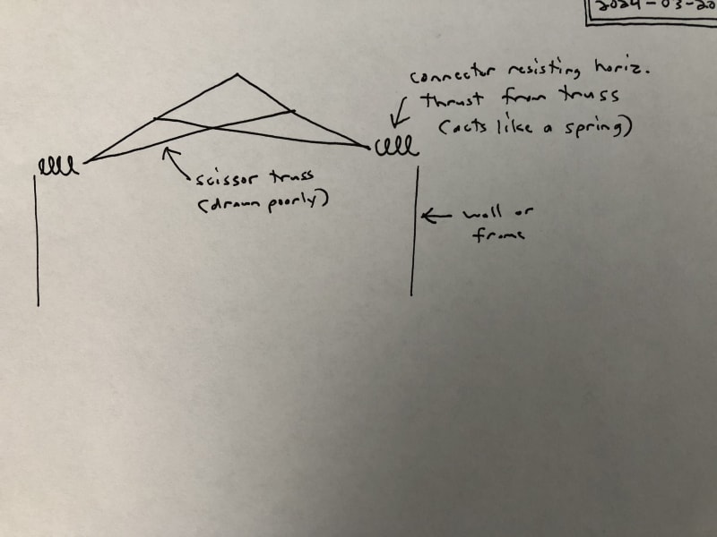
Here's a sketch:
truss_thrust_-_2024-03-20_ibc72t.jpg


I think if you were to model this accurately, the model would need to account for the stiffnesses of the truss, the connector (like a spring), and the wall (or frame) at each end of the truss.

If the wall was infinitely stiff, then all the horizontal displacement would be in the connectors. If the wall had no stiffness, then the displacement would be only in the wall.

StrEng007 said:
This is a foul in design theories...
In general, I don't see the harm in modeling the truss as pin/roller as long as the supporting structure can accommodate the horizontal deflection. As far as the truss goes, if the pin/roller assumption was made and the actual structure had significant stiffness to resist the thrust, I don't think this would adversely affect the truss. If anything, the tension forces in the bottom chord(s) would be relieved. In this particular case, there would be some benefit to the connector displacing, as you mentioned.

StrEng007 said:
No engineer in their right mind designs wind walls to cantilever from the ground up to the point of truss bearing
I've done this before. Given, it was for unique circumstances. To your point, though, others have suggested that I'm not always in my right mind.
 
Eng16080 said:
In general, I don't see the harm in modeling the truss as pin/roller as long as the supporting structure can accommodate the horizontal deflection.
I think my issue got misinterpreted. I'm saying it a foul because:

1. For most walls that are designed to span vertically, the top connection will have to impart a horizontal reaction to the truss in order to get into the diaphragm. Even though there may be some horizontal deflection in the wall, at 175 MPH Exp D, I cannot allow the top of wall to go unsupported in the X-direction. No matter how much displacement occurs to keep the "truss designer happy", the displacement cannot be infinite and I must catch the top of the wall.
2. The truss designer takes no such loading into account. By assuming they have a roller at one end, this alleviates the need to consider that axial load in the truss (unless I specify it to them, which I've seen 90% of engineers don't).
3. The foul is that very rarely are items #1 and #2 both discussed, argued, and agreed upon by the EOR and truss designer.

Note: I realize I'm scrutinizing a process that has been done for a long time without many issues. I've done plenty of building designs with reviews on delegated common truss applications for high wind. What I'm pointing out here is merely what I interpret to be a broken, or fractured, link in the chain. Most other engineers in my jurisdiction (the one I perform design work for) don't want to rock the boat in a county that already has high demands. The buildings I design have the possibility of experiencing a true design event every hurricane season, so you can imagine this has been an ongoing process of me trying to break things down to the most simplistic form to maintain my own sanity.

 
The truss isn't "catching" the wall - it is simply an intermediate connector that simply transfers the horizontal wall thrust up into the diaphragm along the truss top chord. This isn't a global axial force on the truss but a quickly diminishing axial load in the top chord.

 
StrEng007, I understand now what you’re getting at. My apologies for going off on the wrong tangent above.

Your concern is in transferring a lateral force from the wall into the truss and ultimately into the roof diaphragm. Basically a drag strut type deal, or perhaps more like a reverse drag strut.

I can see how this would be difficult for the truss designer to take into account. You would need to somehow apply the lateral load to the truss, but the support or reaction would be along the top of the truss at the sheathing, or wherever the diaphragm is located.

I think in most cases with a typical truss geometry there is probably no issue with this connection. The length of the truss that feels this load is likely minimal under normal conditions as it probably only takes the first foot or two of sheathing to transfer the load out of the truss.

Your point is good though. It’s possible that a truss geometry might exist which could be problematic, and this would likely be overlooked by the truss designer.

I imagine this might be accounted for to some extent by applying the lateral force to the roller end of the truss. The truss would then have to transfer this load to the pinned end. This obviously isn’t accurate, but is likely conservative, maybe even very conservative.
 
You may find this document interesting - it's from one of the big truss manufacturers here

I have also gone down the rabbit hole of trying to resolve thrust deflections at the top plate and have come up with a variety of solutions
On one job I specced a ply diaphragm at the ceiling level...it was all good until I turned up to look at it and saw how much effort went into it
Then I questioned whether 5-10mm of deflection was really worth the cost and effort....
Other jobs I have lived with it, or used a plasterboard ceiling diaphragm, or upgraded the wall top plate to get greater stiffness

My general assumption is that the ceiling restrains a lot of it
Typically here at least you will either pretty rigid end supports (portal frame with tie at knee level or solid wall) at each end, so the thrust deflection there is basically 0
The deflection is a maximum in the middle so you can use the ceiling to restrain it and detail a nice tie to your end walls
 
JAE said:
The truss isn't "catching" the wall - it is simply an intermediate connector that simply transfers the horizontal wall thrust up into the diaphragm along the truss top chord. This isn't a global axial force on the truss but a quickly diminishing axial load in the top chord.

Eng16080 said:
The length of the truss that feels this load is likely minimal under normal conditions as it probably only takes the first foot or two of sheathing to transfer the load out of the truss.

This is really good. I guess that's why y'all are MVPs.
So while that load transfer is present, it's really just a local effect on the truss and really it's the diaphragm that does the lion's share of the work.

This theory provides just enough to make the wall supported without getting bogged down with the whole truss theory, pin/roller issue.

Any chance this is discussed ANYWHERE in a technical paper, book, etc.? I'm thinking it's slim to none to find these words written out as well as you two have put it.
 
I’m not aware of a specific reference that gets into this, but perhaps there is. I think this falls into the category of the many things that are often overlooked or disregarded in design (and rarely discussed) which have a 99 percent chance of never being an issue. Of course, there is always that other 1 percent.

In this case, to potentially be problematic, I’m picturing a truss with a tall heel height, where there isn’t a diagonal web member intersecting the bottom chord at the support location and where the trusses don’t have a diaphragm along the bottom and aren’t laterally braced along the bottom chord. In this case, with the wind load from the wall going into the truss bottom chord, it seems that the bottom chord would likely buckle under compression. The conditions noted would likely only occur with an overall poor design. For example, a roof truss would almost always need bottom chord bracing to be considered properly designed.

I will admit that I’ve completed many designs without giving much thought to this condition. It’s one of those things you only really start to notice when you take an in depth look at the load path.

Thanks for the great question. Thinking through and discussing problems like this make us all better engineers.
 
it's really just a local effect on the truss and really it's the diaphragm that does the lion's share of the work.
Yes, correct in my view.

 
Status
Not open for further replies.

Part and Inventory Search

Sponsor