Hello All,
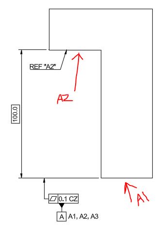
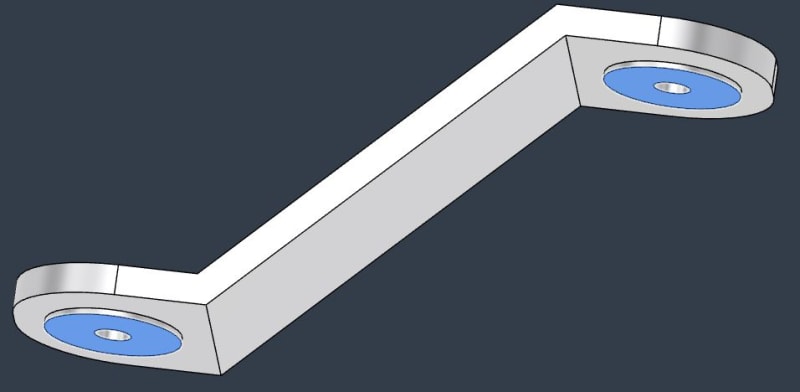
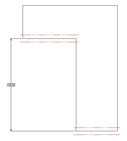
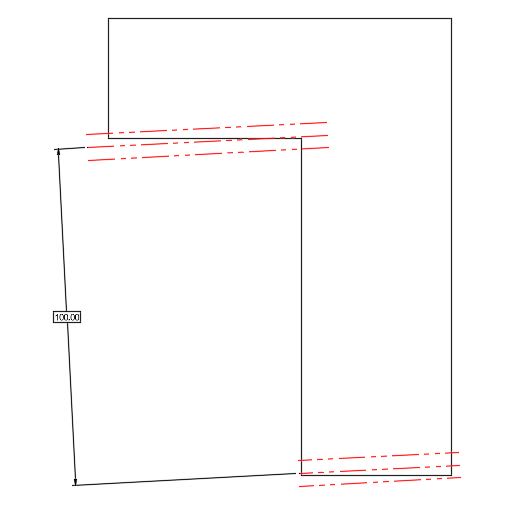
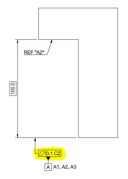
I received a customer print for review with the following callout for [Flatness | 0.1 CZ] for the two identified surfaces. I created an example with a simplified model below, but kept all of the notes/callouts/etc. the same as the customer print.
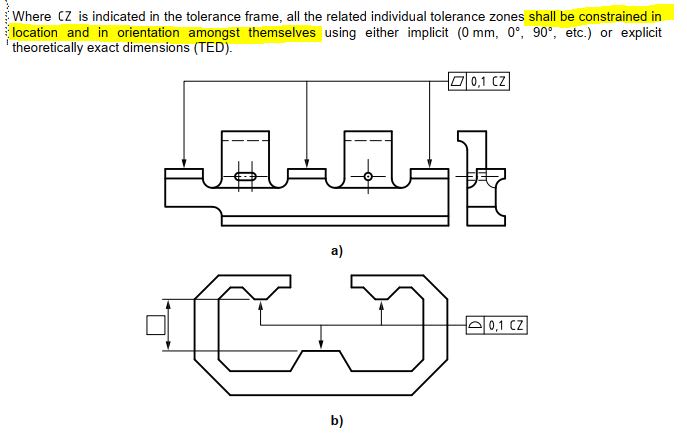
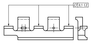
My experience is limited with ISO GPS, but I understand the concept of CZ when applied to co-planar surfaces (as shown in the second image). I'm just a little confused on what the tolerance zone will look like in this example, with the two offset surfaces. Is this still just a form control? Do I treat it as two separate (but parallel) tolerance zones, and ignore the basic offset?
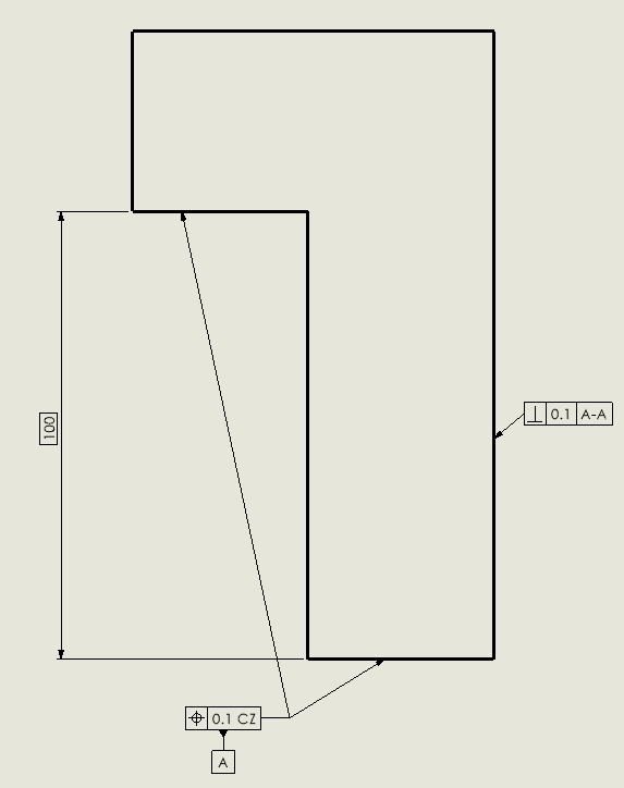
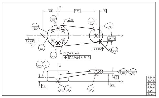
Second image pulled from ISO 1101 for reference
I received a customer print for review with the following callout for [Flatness | 0.1 CZ] for the two identified surfaces. I created an example with a simplified model below, but kept all of the notes/callouts/etc. the same as the customer print.
My experience is limited with ISO GPS, but I understand the concept of CZ when applied to co-planar surfaces (as shown in the second image). I'm just a little confused on what the tolerance zone will look like in this example, with the two offset surfaces. Is this still just a form control? Do I treat it as two separate (but parallel) tolerance zones, and ignore the basic offset?

Second image pulled from ISO 1101 for reference


