Continue to Site

Eng-Tips is the largest engineering community on the Internet

Intelligent Work Forums for Engineering Professionals

  • Congratulations KootK on being selected by the Eng-Tips community for having the most helpful posts in the forums last week. Way to Go!

Load Distribution on Elements 3

Status
Not open for further replies.

Tygra_1983

Student
Oct 8, 2021
121
Dear all

I am currently working on a hypothetical project for the following structure:
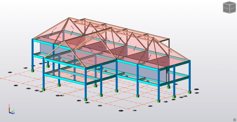
House_Project_Pic2_uru3ee.png


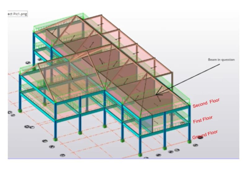
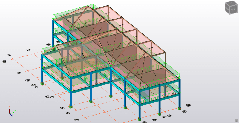
Firstly, I am tackling the load distrubtion on beams in kN/m from an applied area load in kN/m^2. I am analysing the load that comes from the floors including the imposed load which is 2.95 kN/m^2. You can see how the load is distrubited in the following figure:
House_Project_Pic1_mcazrf.png


I am confused how the load has been distrubuted to the following beams. The distributed load changes after the intersection of the wall.
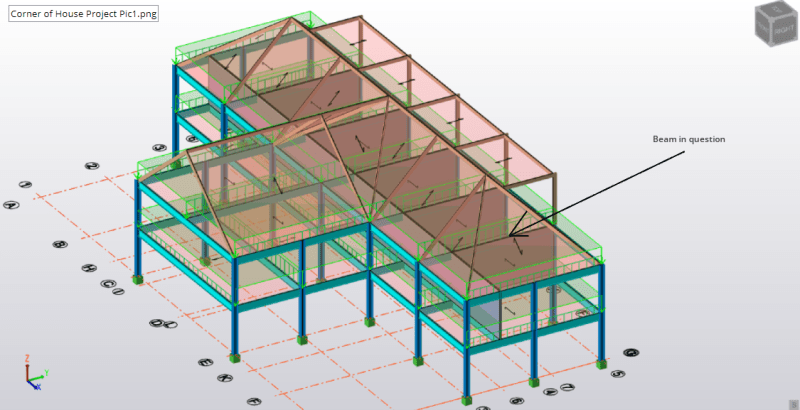
beam_in_question_d9mxye.png


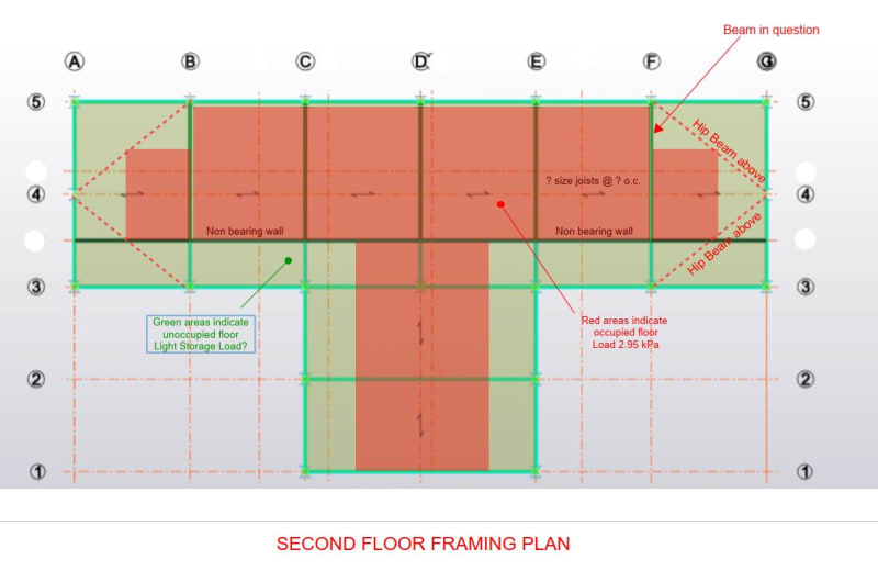
To get the UDL I multiply 2.95 kN/m^2 by 5m (the panel widths) which gives 14.75 kN/m. However, this load does not extend across the whole beam. It reduces to 11.8 kN/m.
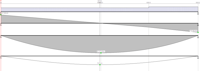
Screenshot_2024-09-17_122440_oj5nyb.png


I guess the wall has something to do with this change in load, but I don't know why. When I look on the plan I feel that the beam should be 14.75 kN/m all the way along the beam; that is the area load should be multiplied by the panel width to get the load in kN/m.
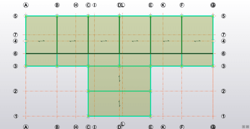
First_Floor_Pic_ehcj8k.png


Why is this happening? Thank you in advance and I hope I have explanied myself clearly enough.
 
Replies continue below

Recommended for you

It's been a long time since I first posted and there's no-one?
 
I don't know how Tekla works but apply 1kN/mm2 and review the loading. I don't think the wall should affect the load distribution. You can duplicate the model and compare the models; one with walls and one without.
 
Quick follow up, tekla has a certain mesh function to distribute load, right? Decompose something -something ...how does that work?
 
We don't know why the load changes. Ask your instructor.
 
Its okay, guys, I just removed the steel beam from the top of the wall and I got a constant load of 14.75 kN/m.
 
You had a wall and a beam in the same location in your model. The software was applying a portion of the distributed load directly to the wall panel and the remainder to the steel beam which is why when you looked at the beam the load stepped down where the wall co-existed.

You said you deleted the beams is your intent for the walls to support the loading or the steel beams. From your original model I would have guesses these walls were just partitions and the steel should be doing the work so would recommend deleting the walls and keeping the the steel beams.
 
Thanks for your explanation, Celt, and I will do what you say.
 
@Tygra:
"...and I will do what you say."

Please don't just do that because I said to. Figure out for yourself what the function of the walls is intended to be. If they are intended to be load bearing then keep them, if they are masonry or concrete frame the short beam to the wall end if they are wood or cold-formed walls then I would say add a steel post at the end to support the shorter steel beam.

All this to say if you don't understand the function of the elements you are modeling then you aren't ready to build the model yet. In generally it is best for you the designer to have already formed the load paths either in your head or through free body diagrams or stick model sketches before beginning the computer model, the computer model should be dictated by your desired load path not the other way around.
 
Celt83 said:
All this to say if you don't understand the function of the elements you are modeling then you aren't ready to build the model yet. In generally it is best for you the designer to have already formed the load paths either in your head or through free body diagrams or stick model sketches before beginning the computer model, the computer model should be dictated by your desired load path not the other way around.

Well, most load paths I get. This was one load path amongst many that I was stuck on. Even some of the helpers/members here said they didn't know. Just because there is one case where I don't know should I not try to design the cases that I do know? This project of mine is all about practise. Its hypothetical like I said.
 
CSIESPL INDIA said:
Assume that a certain percentage of the total area load is supported by the wall.
For example, if we assume that 20% of the total load is carried by the wall, then:
Load carried by beam

Can I ask what made you use 20%?

I didn't post it, but strangely some of the other walls the loading was different. The middle wall for example went down to 6.6 kN/m from 14.75 kN/m.

EDIT: would it be the relevant stiffness that would determine how much load share would be between the wall and beam?
 
Tygra_1983 said:
Just because there is one case where I don't know should I not try to design the cases that I do know?
Tygra_1983 said:
Its hypothetical like I said
if it's hypothetical, would it not be a great exercise to get into how the load is distributed and have a better understanding on how the application works?

Reference the decomposition material by Tekla. Element stiffness plays a role here
 
Part of my problem is that you don't label which plan you are showing. The beam in question appears to be on the second level, i.e. the ceiling level. If that is a floor, three edges will not sustain floor load because of roof slope. 2.95 kPa seems high for a ceiling, and if it is a floor load, the loaded area will be reduced because of the reduced headroom due to roof slope.

You need to make a framing plan for first, second and roof levels, with arrows indicating the direction of joist spans and the location of all beams. As it is, there is more than one interpretation for beam loading.

I suggest you drop Grid-lines 6, 7, H, I, L and K for easier understanding (although that is by no means mandatory).

Just a few suggestions. Please do not take offense.

 
BulbTheBuilder said:
if it's hypothetical, would it not be a great exercise to get into how the load is distributed and have a better understanding on how the application works?

Yes, sure, but I can tackle it as I go along. There are many other members in the house other than this one, and I am starting with the roof rafters and working down. My first thoughts were that the beam above the wall will take 14.5 kN/m and it will transmit 14.5 kN/m to the wall. This is because the beam sits on top of the wall. Or at least that's how I modelled it in my head. So, being unsure of this I thought I would remove the beam, but then after Celt's suggestion I thought it would make more sense to use a beam to take the load rather than using a bearing wall.

Thank you for your suggestion.

BAretired said:
Part of my problem is that you don't label which plan you are showing. The beam in question appears to be on the second level, i.e. the ceiling level. If that is a floor, three edges will not sustain floor load because of roof slope. 2.95 kPa seems high for a ceiling, and if it is a floor load, the loaded area will be reduced because of the reduced headroom due to roof slope.

I have made this house to have a loft space; if you see there are dormers at the back; it is the floor load. That is why am using the 2.95 kPa: 1.35*0.5 + 1.5*1.5 = 2.95.

BAretired said:
I suggest you drop Grid-lines 6, 7, H, I, L and K for easier understanding (although that is by no means mandatory).

Yes, sorry about that. I originaly had some walls on these grid lines, and I can't seem to delete them. clicking on the grid line to highlight it and pressing delete does not seem to be working.

 
The occupied area is shown in red below. The beam in question carries only partial live load, so it is understandable that the load to the beam in question would vary. But it's not a major difference and for simplicity, you may wish to use the same size beam on Gridlines B to F inclusive. I know I would.

You should label joist sizes, beam sizes and wall designation on plan. If you prefer, you could label walls W-1, W-2 etc. and detail them elsewhere.

CaptureS2_qnmery.jpg


Capture_naebtv.jpg
 
Yes, BAretired, for those areas (not in red) I would use the loading for roof space, which on my loading sheet is 1.35*0.25 + 1.5*0.25 = 0.71 kN/m^2. I have learned that its good to group members, so I would use the same beam size for B-F.

In regard to labelling the joists and wall etc I would have to import the image to sketch up and do it (more work), as I don't have Autocad and I'm not sure if you can make a labelled diagram in Tekla.

 
The first mention of Tekla was by BulbTheBuilder. Prior to that, I was not aware what software you were using (not sure how BtB knew).

Tygra 1983 said:
I am currently working on a hypothetical project for the following structure:

Not sure what exactly you are hoping to accomplish in this thread, but it seems to me you will need graphical software capable of labeling various items on plan, erasing grid names and making changes to the drawing as design progresses. Finally, you will need to show your design on a drawing.

I have never used Tekla, have been retired since 2008 and at 91, am too long in the tooth to learn the intricacies of a new software package, but reading the Tekla ads, I would suspect they have all the features you need for this project. But of course, learning a new piece of software takes time, time which you may not be prepared to spend while studying engineering.

How does your instructor expect you to submit your design on this project?
 
BAretired said:
Not sure what exactly you are hoping to accomplish in this thread

I didn't know why the loading was changing on the beam along its length (the one I labelled), and also all the beams at the same level that were parallel to it - members B to F. So, it has been answered somewhat.

BAretired said:
I have never used Tekla, have been retired since 2008 and at 91
Wow, that's incredible. Praise God for your long life. I guessed you were retired because of your username, but I didn't think you would be 91.

BAretired said:
How does your instructor expect you to submit your design on this project?

I don't have an instructor. Due to personal reasons I am not working at the moment. I graduated University last year; I am a mature student born in 1983, hence, my username. I did have some work back in the winter but it didn't work out. Then we submitted the drawings using Autocad. Thus, I am not too concerened with submitting the drawings. Although I am making a report document in Word with the calculations. So, this project it just for practise. However, now you say, perhaps I should take some time to make some structural drawings, so it's a realistic as possible.
 
BtB said:
Reference the decomposition material by Tekla. Element stiffness plays a role here
I didn't know why the loading was changing on the beam along its length (the one I labelled), and also all the beams at the same level that were parallel to it - members B to F. So, it has been answered somewhat.
Was there anything useful to you in this doc?

BAretired said:
The first mention of Tekla was by BulbTheBuilder. Prior to that, I was not aware what software you were using (not sure how BtB knew).
I used the trial version almost a decade ago when one of my previous companies was deciding which application to use, we ended up with Midas Gen. I know Tekla is common in UK

Tygra_1983 said:
Yes, sorry about that. I originaly had some walls on these grid lines, and I can't seem to delete them. clicking on the grid line to highlight it and pressing delete does not seem to be working.
There is a direct modification button that you need to use for the modifying elements (including grids). Check if that feature is still active in newer versions.

BAretired said:
I have never used Tekla, have been retired since 2008 and at 91, am too long in the tooth to learn the intricacies of a new software package, but reading the Tekla ads, I would suspect they have all the features you need for this project. But of course, learning a new piece of software takes time, time which you may not be prepared to spend while studying engineering.
"Praise God for your long life." And thank you for spending time on this forum helping us each day! it is greatly appreciated!! Star for you!!

Tygra_1983 said:
I don't have an instructor. Due to personal reasons I am not working at the moment. I graduated University last year; I am a mature student born in 1983,
You are doing great! You are a smart person; I have seen your posts, and I have no doubt. Pray all goes well for you. Keep it up and remember, all will be well!!

You get free time try learning Revit. I have found it to be more efficient than Autocad for structural drawings.
 
BulbTheBuilder said:
Was there anything useful to you in this doc?

When I click the link it goes to 'page not found'.

BulbTheBuilder said:
There is a direct modification button that you need to use for the modifying elements (including grids). Check if that feature is still active in newer versions.

I will have look for that. Unfortunately, my student trial expires in about 10 days. Shame, I was starting to like Tekla Structural Designer. At Uni I used SAP2000 and was accustomed to using that. It took me a while to enjoy Tekla.

BAretired said:
have never used Tekla, have been retired since 2008 and at 91, am too long in the tooth to learn the intricacies of a new software package, but reading the Tekla ads, I would suspect they have all the features you need for this project. But of course, learning a new piece of software takes time, time which you may not be prepared to spend while studying engineering.
BulbTheBuilder said:
"Praise God for your long life." And thank you for spending time on this forum helping us each day! it is greatly appreciated!! Star for you!!

Yes, thank you, BAretired. You have helped on many of my posts since I joined the forum - thank you!

BulbTheBuilder said:
You are doing great! You are a smart person; I have seen your posts, and I have no doubt. Pray all goes well for you. Keep it up and remember, all will be well!!

Thank you for your very kind words, BulbTheBuilder. Its encouragement like that, that keeps you going! That and the help from the Lord! Thank you for your prayers.

BulbTheBuilder said:
You get free time try learning Revit. I have found it to be more efficient than Autocad for structural drawings.

I did use Revit at University. Even though I can still gets books out at the Uni Library, I have lost all access to their online services because I am not enrolled anymore. Revit was really good, but I thought it was more of an architects tool?

Just a quick question to you guys: When I was working, my employer relied solely on the computer software for the design and verification of members. No hand calcs or anything to validate the computer results. The only hand calcs he did was to calculate the loadings on the members. He did, for the most part, only work on residential buildings - loft conversions and extensions etc. I was quite dissapointed by this, even though it makes the job alot longer. Just wondering if youy guys think that it good practise?
 
Status
Not open for further replies.

Part and Inventory Search

Sponsor