Continue to Site

Eng-Tips is the largest engineering community on the Internet

Intelligent Work Forums for Engineering Professionals

  • Congratulations SSS148 on being selected by the Eng-Tips community for having the most helpful posts in the forums last week. Way to Go!

Wood frame Balcony Baseplate Connections - How do they ever work?

EngDM

Structural
Aug 10, 2021
690
A situation I come across quite often is a wood framed balcony, with some sort of aluminum or steel guardrail with a simple 5"x5" baseplate and 4 lag screws holding it down. I have had a hard time getting the calcs to come remotely close to working. In the NBCC we require an outwards load of 1.0kN live, factored goes up to 1.5kN. For a typical guardrail 3'6", this generates a moment of roughly 1.6kN-m at the base of the post. With a 1/2" edge distance of the lag bolt on the 5"x5" baseplate, you get nearly 16kN of uplift on the pair of anchors.

How does this ever work? I have seen stamped drawings showing the lag bolts as 3/8"Øx4" long. The only way I can get this remotely close is if I take the entire lag bolt embedment depth as threaded and rely on the whole length. But that doesn't account for the effective threaded lengths discussed in O86.

I am hoping I am missing something that makes the calcs turn out a bit better.
 
Replies continue below

Recommended for you

I can't get them to work either. Also, the lag likely ends up in some unfortunate spot like between plies. On a recent job, we added an extra band on the outside so we could clamp the post between the members. Gave the look of bottom mount. This was for a job with 4x4 posts covered in a Trek sleeve though.
 
I can't get them to work either. Also, the lag likely ends up in some unfortunate spot like between plies. On a recent job, we added an extra band on the outside so we could clamp the post between the members. Gave the look of bottom mount. This was for a job with 4x4 posts covered in a Trek sleeve though.
In practice I am sure they are completely fine for the loads they actually will experience (I know I wouldn't be running into a balcony several stories up). How are any of these drawings ever stamped if the numbers just don't work.

I've had more luck with a side mounted baseplate on the face of the edge member to avoid going between two ply's, but even still you get some ridiculous pullout values.
 
Honestly, I've wondered the same. Working on residential (homes, not towers), however, I've been fortunate enough that municipalities simply accept (in my locale, that is) a note stating that all guards are to conform to the OBC clauses specific to this issue. I was never able to make the calcs work either, so I leave it up to the railings contractor to provide details.
 
Honestly, I've wondered the same. Working on residential (homes, not towers), however, I've been fortunate enough that municipalities simply accept (in my locale, that is) a note stating that all guards are to conform to the OBC clauses specific to this issue. I was never able to make the calcs work either, so I leave it up to the railings contractor to provide details.
But then when they provide details, are they stamped? Where I practice, guardrail shops are stamped and show the loads they are designed for. Someone had to have gotten them to work somehow. Either that or they have load tested their assemblies and put the support of their guardrail (I.E. supporting the beam below against rotation) on the EOR.
 
Honestly, I've wondered the same. Working on residential (homes, not towers), however, I've been fortunate enough that municipalities simply accept (in my locale, that is) a note stating that all guards are to conform to the OBC clauses specific to this issue. I was never able to make the calcs work either, so I leave it up to the railings contractor to provide details.
I typically do the same unless specifically asked to do a design. The worst is trying to "fix" ones that are already constructed. I try to send those to my competitors who have a more liberal view of the laws of physics.
 
But then when they provide details, are they stamped? Where I practice, guardrail shops are stamped and show the loads they are designed for. Someone had to have gotten them to work somehow. Either that or they have load tested their assemblies and put the support of their guardrail (I.E. supporting the beam below against rotation) on the EOR.
I imagine enough CYA stuff on them to make it pretty worthless.
 
But then when they provide details, are they stamped? Where I practice, guardrail shops are stamped and show the loads they are designed for. Someone had to have gotten them to work somehow. Either that or they have load tested their assemblies and put the support of their guardrail (I.E. supporting the beam below against rotation) on the EOR.
Oh yes, they are. I just don't want to take ownership of something that clearly doesn't work. This is in the case of manufactured railings, by the way.

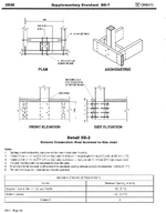
For simpler situations, the OBC supplementary bulletins have multiple pages outlining accepted connections for a variety of situations. These are for wood railings based on 4x4 posts and whatnot. I refer to those and specify which details to use and where if the client doesn't mind having wood guards.

EDIT: It's SB-7. Here's an example if you haven't seen this before (not sure where you are). Ignore the older year...1745247468259.png
 
Oh yes, they are. I just don't want to take ownership of something that clearly doesn't work. This is in the case of manufactured railings, by the way.

For simpler situations, the OBC supplementary bulletins have multiple pages outlining accepted connections for a variety of situations. These are for wood railings based on 4x4 posts and whatnot. I refer to those and specify which details to use and where if the client doesn't mind having wood guards.

EDIT: It's SB-7. Here's an example if you haven't seen this before (not sure where you are). Ignore the older year...View attachment 8505
See this makes sense. Clear load path, shear only not really pullout.

Now I just need a solution for aluminum guards.

It sucks because other people have stamped stuff that, by any method aside from testing that I try, just doesn't work. So now I am in a bit of a pickle because the client comes in with a certain expectation to just do what they've always been doing.
As far as I can tell, it won't ever work so you're left with few choices -

1) Outsource and have a different engineer stamp the railings and carry them in your fees. Not great but technically an option. Have your stamp clearly outline that the railings are not in your scope and are covered by others.
2) Leave for shop drawing process by manufacturer if possible.
3) Just accept it for what it is on a case-by-case basis and do your best (if you're OK with it, that is).
Yea we usually outsource it when we are the EOR, but we picked up a client to stamp their shops (not sure why they left their last engineer) and I was trying to get their old details to work.

I've seen the exact detail by one of the biggest firms nationwide up here, so there HAS to be a way to get this to work right? ...right?
 
Outsource and have a different engineer stamp the railings and carry them in your fees.
No. No no no no no.

If you're the EOR, it's your building. The amount of trust you put in the delegated engineer is up to you, but at the end of the day the EOR is responsible for the whole kit and caboodle. (Whatever a caboodle is.) Have a guardrail that has been tested under the supervision of a PE with adequate proof to back it up? Then by all means, lean on it to say the railing works. But it's the EOR's responsibility to ensure that whatever they are attaching to is strong enough. In other words, you can farm out portions of the load path, but ensuring the load path is continuous and connecting all the disparate bits together is the EOR's job. This is doubly true if you're the one hiring the specialty engineer. Just because another engineer said it works doesn't mean that it does. If you know something doesn't work but let it slide because another engineer sealed it, you need to take a good hard look in the mirror. Becuase you might as well have just sealed it.

@EngDM , the provided details rarely work. I usually use them as a starting point, but remember that all they care about is the diameter of the fastener (they need to pick a hole size for the plate) and then a minimum embedment to get the values, probably making a bunch of ideal assumptions that won't actually happen. So I typically chuck everything but the fastener diameter and start over. The railing designer doesn't "know" all fo the conditions - maybe they assumed it was an interior railing? So now I have to account for moisture, etc. Wind on an exterior rail if it's tight enough (or glass). The blocking may need to be reinforced, but I often try to use blocking shallower than the joists so I can put a plate and bolts on it. Then I have to determine fastening of the blocking to the joists/beam(s).

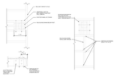
Here's an example of a glass railing on a deck next to a lake I did a few years ago. The manufacturer's details called for (4) 5" lags, "substrate by designer" or something like that.
1745254612767.png
 
Yeah, I definitely agree with pham's comment above. I doubt anybody really cares about the building like the EOR does. I wouldn't want to delegate part of the job that doesn't even pass a reasonable sanity test on my part. Delegated/outsourced (whatever we're calling it) work tends to be done under a microscope where they're only concerned about that very specific thing and not how it relates to the overall building / load path. "substrate by designer" is a perfect example. For a detail like this, the substrate and/or connection to it is almost guaranteed to be the weak point.

There was a similar thread here not long ago with a connection like this. I think we all concluded it was pretty sketchy. I'd bet a lot of these are attached to nothing more than the deck boards.
 
There was a similar thread here not long ago with a connection like this. I think we all concluded it was pretty sketchy. I'd bet a lot of these are attached to nothing more than the deck boards.
You would be correct.

Had a big apartment building years ago with this issue. They only noticed it because they did work on a balcony and realized the outer 2 screws barely hit the 2x rim and the inner two screws were only in the trex. Had to shut down like 50 balconies for a while until they could open them all up and add blocking and repair. Since then I've always specified a minimum of double 2x on rim of decks.

But I rarely detail railings or posts. I just say railing per code normally.
 
I have had the same problem getting calcs to verify the attachments. I have seen the lag callout information to be a problem in that the specifier was not familiar with "the lag screw world".

For those reading this thread, the conversation about lag screws is important if you have not investigated lag screws before. Length and thread length are not the same, and rarely is length = thread length. As you get to the 4" and longer lag screws, your mind needs to estimate that slightly over half of the length is threaded. So, when calcs say you need 4" of embedment (i.e thread length) you are talking about a 7" lag screw or longer. I think you can special order lags that are full length threaded but your callout needs to state this. Requesting 7" lags gets you about 4"embedment. Only extremely short lags approach full-thread as the standard option.

Also, installing longer full-thread lags sometimes snaps them off before they seat. Takes more torque to drive them. Better use the largest pilot hole allowed.
 
No. No no no no no.

If you're the EOR, it's your building. The amount of trust you put in the delegated engineer is up to you, but at the end of the day the EOR is responsible for the whole kit and caboodle. (Whatever a caboodle is.) Have a guardrail that has been tested under the supervision of a PE with adequate proof to back it up? Then by all means, lean on it to say the railing works. But it's the EOR's responsibility to ensure that whatever they are attaching to is strong enough. In other words, you can farm out portions of the load path, but ensuring the load path is continuous and connecting all the disparate bits together is the EOR's job. This is doubly true if you're the one hiring the specialty engineer. Just because another engineer said it works doesn't mean that it does. If you know something doesn't work but let it slide because another engineer sealed it, you need to take a good hard look in the mirror. Becuase you might as well have just sealed it.

@EngDM , the provided details rarely work. I usually use them as a starting point, but remember that all they care about is the diameter of the fastener (they need to pick a hole size for the plate) and then a minimum embedment to get the values, probably making a bunch of ideal assumptions that won't actually happen. So I typically chuck everything but the fastener diameter and start over. The railing designer doesn't "know" all fo the conditions - maybe they assumed it was an interior railing? So now I have to account for moisture, etc. Wind on an exterior rail if it's tight enough (or glass). The blocking may need to be reinforced, but I often try to use blocking shallower than the joists so I can put a plate and bolts on it. Then I have to determine fastening of the blocking to the joists/beam(s).

Here's an example of a glass railing on a deck next to a lake I did a few years ago. The manufacturer's details called for (4) 5" lags, "substrate by designer" or something like that.
View attachment 8509
I quite like that detail.

The issue I am currently dealing with is that the fabricator went ahead and fabricated all of their plates, assuming it would work since the last engineer stamped it, but now I am wanting changes that they are less than happy to do (understandably). I might just have to scrap using lags, and use a thru bolt with a plate washer to get the bearing to work. But when I've got now 20kN of load to resist between 2 bolts (my original numbers were based on my revised bolt spacing which has since been limited to 3").

I think you can special order lags that are full length threaded but your callout needs to state this.

This is how I called it up just to be safe.
 
20kN of load to resist between 2 bolts
Not too bad if you can use a plate underneath. That's about 4500lbs, right? So a pair of A307 bolts bearing on a 2"x5" plate should do it. So make it a 1/4"x5"x5" plate underneath to keep it all symmetrical and you should be good to go as long as whatever you're clamping it to can take the torsion.
 
Thank you EngDM and PhamENG. I think the idea of thru bolts is probably the way to go. I helped another engineer with extending a deck / balcony a few feet. This was a few years ago when I was helping a friend with a side project when he was swamped.

I have to see what he did for the railing.... I didn't stamp anything for that project, but I did a bunch of the other work. This thread has been a big wake up call for me on wood railings.
For side mounted, my preferred detail is to use a thru bolt to a holdown (simpson DTT2Z or something) which goes directly to the deck joist.

Not too bad if you can use a plate underneath. That's about 4500lbs, right? So a pair of A307 bolts bearing on a 2"x5" plate should do it. So make it a 1/4"x5"x5" plate underneath to keep it all symmetrical and you should be good to go as long as whatever you're clamping it to can take the torsion.
Mine is a side mounted condition in this specific case, but basically that. The restraint of the beam for torsion is on the EOR, but they have specified elements to account for this.
 

Part and Inventory Search

Sponsor