EngDM
Structural
- Aug 10, 2021
- 690
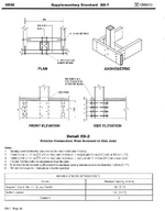
A situation I come across quite often is a wood framed balcony, with some sort of aluminum or steel guardrail with a simple 5"x5" baseplate and 4 lag screws holding it down. I have had a hard time getting the calcs to come remotely close to working. In the NBCC we require an outwards load of 1.0kN live, factored goes up to 1.5kN. For a typical guardrail 3'6", this generates a moment of roughly 1.6kN-m at the base of the post. With a 1/2" edge distance of the lag bolt on the 5"x5" baseplate, you get nearly 16kN of uplift on the pair of anchors.
How does this ever work? I have seen stamped drawings showing the lag bolts as 3/8"Øx4" long. The only way I can get this remotely close is if I take the entire lag bolt embedment depth as threaded and rely on the whole length. But that doesn't account for the effective threaded lengths discussed in O86.
I am hoping I am missing something that makes the calcs turn out a bit better.


