Continue to Site

Eng-Tips is the largest engineering community on the Internet

Intelligent Work Forums for Engineering Professionals

  • Congratulations cowski on being selected by the Eng-Tips community for having the most helpful posts in the forums last week. Way to Go!

Whats the deal with hip roofs

Apr 25, 2024
24
I'm sure this topic comes up quite a lot. I have seen soooooo many hip roofs framed. We all know about the lateral thrust at the corners/lower support if there is nothing holding up the edge of the ridge or if the roof is framed with trusses. So why in the world are these roofs still standing for years? some of them I've seen don't even have hanger for the jack rafters, they are just toe nailed into the end of the ridge beam or an angle. I theorize that the sheathing provides some kind of support. But in theory if nothing hold up the ridge beams then the thrust in jack rafters can be quite high. I've seen older framing books show tension rings around the lower framing, or trusses,..... all this to say.... what's the deal with these hip roofs that are clearly not being structurally analyzed. Thoughts anyone?
 
Replies continue below

Recommended for you

This question comes up quite frequently here.

If there's a flat ceiling, the outward thrust can be resisted by ceiling joists connected to the rafters at the wall top plate (or slightly higher).

If there's no flat ceiling (cathedral ceiling), then the thrust would be resisted by a combination of restraint at the top of wall and by the roof sheathing. Most engineers won't want to rely on the roof sheathing for resistance, although it's definitely helping in reality. Restraint at the wall can be provided by a tension ring and/or other elements capable of resisting an outward force (like beams loaded horizontally). Even without deliberate detailing, most walls will still provide some restraint, especially if the walls are not especially long and/or there are intermediate perpendicular walls tied to them.
 
Most things stand, but a lot of older lower slope hip roofs definitely have sags or separation of the rafters along the hip-nailer.

The folded plate action with the sheathing helps hips last a lot longer than valleys just due to the fact that the wood framing is being compressed at the connection.

In new construction I'm okay with hips being just nailers most of the time. Valley's I'll always design as beams.
 
This question comes up quite frequently here.

If there's a flat ceiling, the outward thrust can be resisted by ceiling joists connected to the rafters at the wall top plate (or slightly higher).

If there's no flat ceiling (cathedral ceiling), then the thrust would be resisted by a combination of restraint at the top of wall and by the roof sheathing. Most engineers won't want to rely on the roof sheathing for resistance, although it's definitely helping in reality. Restraint at the wall can be provided by a tension ring and/or other elements capable of resisting an outward force (like beams loaded horizontally). Even without deliberate detailing, most walls will still provide some restraint, especially if the walls are not especially long and/or there are intermediate perpendicular walls tied to them.

Right so the ceiling joists perpendicular to the ridge pick up the thrust. I was talking about the jack rafters. those have quite a bit of thrust in them. And the last ceiling joists at the end of the ridge beam arent detailed or fastened with enough connected to carry that thrust. At least not that I have ever seen.
 
I theorize that the sheathing provides some kind of support.

That. This probably deserves a sketch (and let me know if it does) but I'm short on time so let's try prose first.

1) Often you have some version of a ceiling tension tie both directions.

2) With the tension ties is play, the things almost work like regular tied rafters hitting a ridge board.

3) If the sheathing restrains the ridge board from translating up the ridge, #2 is a complete load path that works.

4) If the framing is symmetrical and the load uniform, the demand on mechanism #3 is lessened because your ridge boards just bump into each other.
 
You may find this report illuminating: Full-Scale Load Test on a Valley and Hip Roof
At first glance this seems it would answer many questions. but after reading it, it leaves some questions. for one it was not really a true hip roof. what was the bottom framed to? how were the rafter jacks connected for the hip side? I know im sounding negative. but I do actually appreciate you sending this over
 
seen don't even have hanger for the jack rafters, they are just toe nailed into the end of the ridge beam or an angle.

But in theory if nothing hold up the ridge beams then the thrust in jack rafters can be quite high.
They have made changes to hip framing over the years that have made improvements, with the main one being a requirement that the end of the ridge board have a vertical brace rather than relying on the 3 common rafters at the end of the ridge board. I too am amazed at the hips roofs in snow areas that have survived. In the shade and shelter part of the US, not so amazing.

1745859723312.png

I realize everyone does not use the same terminology in any arena. In this conversation, I see ridge beam referenced. Are you talking about a ridge board or an actual ridge beam? A ridge board is held up by the common rafters, while ridge beam holds up the common rafters. I also saw a reference to a jack rafter framing into to the ridge beam. In the terminology where I have worked, the only parts of a hip that directly connect to the ridge board are the hip rafters (main diagonal, 2 per hip) and a single common rafter aligned with the end of the ridge board. The hip rafter is what all the hip jacks connect to I think.

The basic hip roof has a ridge board, common rafters, hip rafters, valley rafters, hip jacks and valley jacks. The ceiling joists are parallel to the common rafters that frame into the side of the ridge board but have different orientations at the hip area.
 
Do you mean to say that you turn the cieling joists 90degrees at the end?

Yup. In some very old buildings, I've seen complete sets of tension ties across the entire building in both directions. The one set placed above the other. In more modern buildings its usually a turning of the ceiling joists as you say.

With prefab truss systems, it's the corner jacks of course. 8' setback or whatever.

There are a great many prefab trussed hips where the ridge beam will not check out by the numbers. 2x6 or 2X8 at ski lodges or whatever. I suspect this is why we also do not see problems there.
 
I was talking about the jack rafters. those have quite a bit of thrust in them.
Unless I misunderstand the framing (a sketch would be useful), there could still be ceiling joists tied to the jack rafters. As noted by KootK, at some point the direction of the ceiling joists would be changed. Otherwise, the ceiling joists would interfere with the jack rafters near the wall. Normally, I'll show a double ceiling joist beam something like 2 ft from the wall which supports the short ceiling joists running in the other direction.
 
They have made changes to hip framing over the years that have made improvements, with the main one being a requirement that the end of the ridge board have a vertical brace rather than relying on the 3 common rafters at the end of the ridge board. I too am amazed at the hips roofs in snow areas that have survived. In the shade and shelter part of the US, not so amazing.

View attachment 8795

I realize everyone does not use the same terminology in any arena. In this conversation, I see ridge beam referenced. Are you talking about a ridge board or an actual ridge beam? A ridge board is held up by the common rafters, while ridge beam holds up the common rafters. I also saw a reference to a jack rafter framing into to the ridge beam. In the terminology where I have worked, the only parts of a hip that directly connect to the ridge board are the hip rafters (main diagonal, 2 per hip) and a single common rafter aligned with the end of the ridge board. The hip rafter is what all the hip jacks connect to I think.

The basic hip roof has a ridge board, common rafters, hip rafters, valley rafters, hip jacks and valley jacks. The ceiling joists are parallel to the common rafters that frame into the side of the ridge board but have different orientations at the hip area.
I meant ridge board sorry. Not ridge beam.
what you're calling a hip jack im calling a jack rafter.
 
Yup. In some very old buildings, I've seen complete sets of tension ties across the entire building in both directions. The one set placed above the other. In more modern buildings its usually a turning of the ceiling joists as you say.
Sometimes I see ceiling joists turned at the ends, sometimes not. Even when they are, I've never seen them "tied" to something that looks substantial enough to resist the tension. Probably the ceiling distributes this tension to perpendicular walls in combination with weak axis bending of the typical ceiling joists that run perp to the main ridge. Honestly I'd probably try to complete the load path with something more explicit even though these types of roofs just work.
 
Even when they are, I've never seen them "tied" to something that looks substantial enough to resist the tension.

I feel that you are considering things in terms of "what can I prove with real engineering".

Instead, consider it in terms of "how does this sketchy thing actually work, which I take to be OP's fundamental question.

The "tie" is often the connection to the diaphragm that is the ceiling gypsum. Love it or hate, many structures need it.
 
Normally, I'll show a double ceiling joist beam something like 2 ft from the wall which supports the short ceiling joists running in the other direction.
That is how most of the CJS I have seen were generally framed. Short "joist lookouts" we used to call them, that were 2' or so long and framed from the wall to the last CJ that was perpendicular to the ridge. There is another tension tie that is relied on we used to call a "hog trough". It is centered on each span of CJs and we extended it to the wall the hip jacks that were parallel to the ridge sat on. It provided some tension tie ability.
 
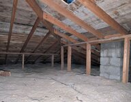
I reviewed an aged hip recently as luck would have it. 16' setback with the short ceiling joists turned about 6' in. Two of the ridge boards are actually snapped flexurally as a result of past loading and poor lumber grading (knots in bad places).

The thing is holding up impressively well in spite of all that.

Hip roofs with symmetry and nominal diaphragms never cease to amaze.

c01.JPG
 
KootK - did you consider adding a plaque somewhere inside that attic?

No, I'm not sure that I want it known that I was there. I just urinated on the side of the chimney to ward of other structural engineers. That, and I've got a wicked addiction to Big Gulps that flares up whenever I have to drive somewhere for work.
 
In addition to everything mentioned above, if the hips line up with the wall corners like most do, then the walls act as little shear walls in each direction to resist the thrust. For the hip to move, the walls would have to overturn.
 

Part and Inventory Search

Sponsor